Light source structure, backlight module and display device

A technology of backlight module and optical structure, applied in the direction of light source, flat light source, lighting device, etc., can solve the problems of uneven light mixing, weak light intensity, and high light intensity, achieve uniform light, reduce contrast, and improve brilliance degree of effect

Active Publication Date: 2022-04-08
RADIANT GUANGZHOU OPTO ELECTRONICS +1
View PDF5 Cites 0 Cited by
  • Summary
  • Abstract
  • Description
  • Claims
  • Application Information

AI Technical Summary

Problems solved by technology

Therefore, the light generated by the light-emitting chip 110 is mainly emitted from the top of the package body 120, so that the light intensity directly above the package body is higher and the light intensity on both sides of the package body is weaker, which will cause a gap between adjacent light-emitting bodies 110a. A dark area is formed, wherein the dark area formed between adjacent luminous bodies 110a in the oblique direction is the most obvious (such as image 3 The dark area R1 shown), which leads to the appearance of the backlight module with a clear contrast between light and dark, and uneven light mixing

Method used


Image

  • Light source structure, backlight module and display device
  • Light source structure, backlight module and display device
  • Light source structure, backlight module and display device

Examples


Embodiment Construction

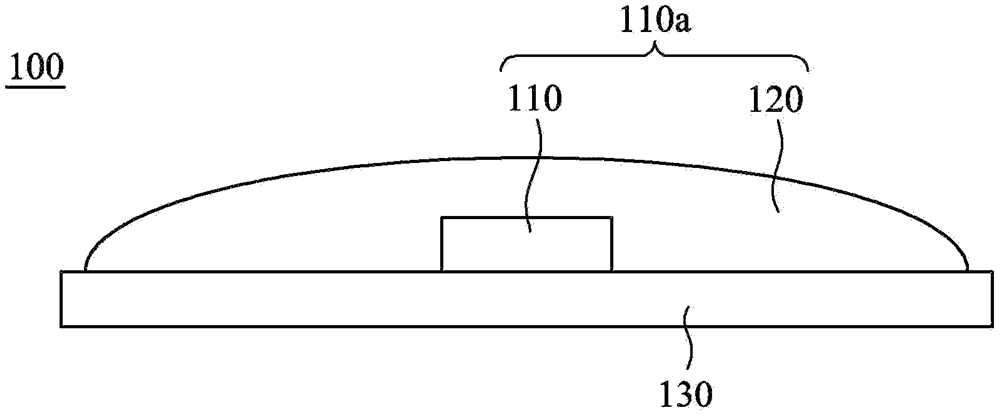
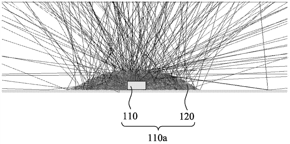
[0038] Please also refer to Figure 4 and Figure 5 ,in Figure 4 is a schematic diagram of a device illustrating a structure of a light source according to an embodiment of the present invention, Figure 5 It is a partial side view of a device illustrating a light source structure according to an embodiment of the present invention. The light source structure 300 of this embodiment mainly includes a substrate 310 , a plurality of light emitting units 320 and a plurality of packaging structures 330 . Wherein, the light emitting units 320 are arranged in an array on the substrate 310 , and each light emitting unit 320 has a central optical axis S1 perpendicular to the substrate 310 . In this embodiment, the central optical axis S1 is a normal line passing through the center of the light emitting surface of the light emitting unit 320 . Such as Figure 4 As shown, in one embodiment, the light emitting units 320 may be arranged in an array along the first direction D1 and th...


PUM


Abstract

A light source structure (300), a backlight module (400) and a display device (500). The light source structure (300) includes a substrate (310), multiple light emitting units (320) and multiple packaging structures (330). The light-emitting units (320) are arrayed on the substrate (310), and each light-emitting unit (320) has a central optical axis perpendicular to the substrate (310). The encapsulation structure (330) respectively and correspondingly covers the light emitting units (320). Each encapsulation structure (330) has a centerline perpendicular to the substrate (310). The central optical axis of the light emitting unit (320) is offset relative to the central line of the package structure (330) along the same direction.

Description

technical field [0001] The invention relates to a light source element, and in particular to a light source structure, a backlight module and a display device. Background technique [0002] A general direct-lit backlight module mainly includes a backplane, a plurality of light-emitting diodes and an optical film. The light emitting diodes are arranged in an array on the back plate, and the optical film is arranged above the light emitting diodes to mix the light generated by the light emitting diodes. [0003] Please refer to Figure 1 to Figure 3 ,in figure 1 depicts the existing light-emitting diode structure, figure 2 is a simulated ray tracing diagram using an existing LED structure, image 3 It is a simulation diagram of the mixed light effect produced by using the existing light-emitting diodes. In the existing light emitting diode structure 100 , the light emitting chip 110 is packaged in the middle of the package body 120 to form light emitters 110 a , and thes...

Claims


Application Information

Patent Timeline
Patent Type & Authority Patents(China)
IPC IPC(8): G02F1/13357
CPCG02F1/133603G02F1/133607G02F1/133611H01L25/0753F21V13/04F21V3/049H01L27/156F21Y2105/16F21Y2115/10
Inventor 朱延专张嘉尹翁巾婷钟翌菁陈昊
Owner RADIANT GUANGZHOU OPTO ELECTRONICS
Why Eureka
Try Eureka