Light conducting plate and manufacturing method thereof

A manufacturing method and technology of a light guide plate, applied in the fields of optics, optomechanical equipment, nonlinear optics, etc., can solve the problem of low luminance of the light guide plate, and achieve the goal of improving light utilization, reducing light loss, and increasing luminance Effect

Inactive Publication Date: 2005-01-26
HONG FU JIN PRECISION IND (SHENZHEN) CO LTD +1
View PDF0 Cites 0 Cited by
  • Summary
  • Abstract
  • Description
  • Claims
  • Application Information

AI Technical Summary

Problems solved by technology

[0006] In order to overcome the defect of low luminance of the light guide plate in the prior art, the present invention provides a light guide plate with high luminance

Method used


Image

  • Light conducting plate and manufacturing method thereof
  • Light conducting plate and manufacturing method thereof
  • Light conducting plate and manufacturing method thereof

Examples


Embodiment Construction

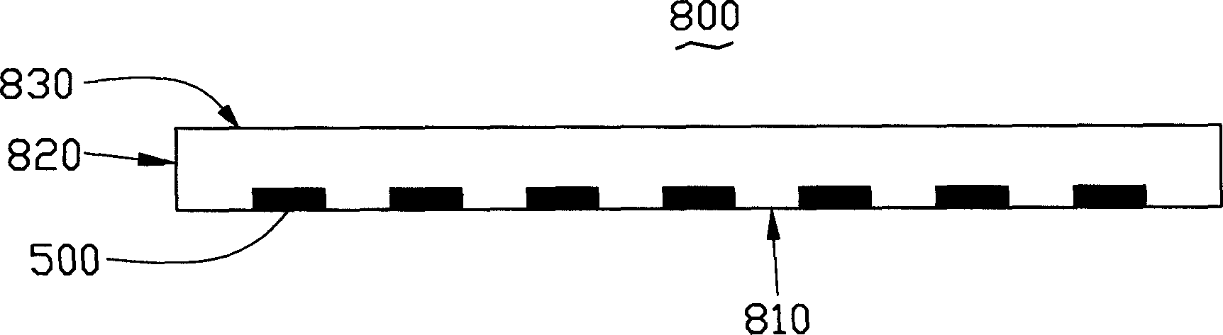
[0021] see figure 2 , the light guide plate 800 of the present invention includes at least a light incident surface 820 , a light output surface 830 and a bottom surface 810 . Wherein, the light-emitting surface 830 is opposite to the bottom surface 810 , and the metal layer 500 with a cylindrical fine structure is embedded in the bottom surface 810 . Since the refractive index of the metal layer 500 is different from that of the material of the light guide plate 800, the total reflection condition of the light is destroyed, and the light is effectively reflected to the light-emitting surface 830 of the light guide plate, which can reduce light loss, make the light output uniform, and increase the brightness.

[0022] see Figure 3 to Figure 10 , is the manufacturing method of the light guide plate of the present invention.

[0023] see image 3 , provide a base 300, the base 300 is made of polymer material, such as polyethylene terephthalate (Polyethylene Terephthalate, P...


PUM


Abstract

This invention relates to a method of light conducting board including steps that making a substrate and covering it with a heat stripping layer on which deposits a sheet metal coating a photoresist, making use of light shield with preliminary design to expose the photoresist, develop the photoresist, etch the sheet metal, peel off the photoresist, and get the substrate with sheet metal designs, offering a male mold and a female mold and setting the substrate with sheet metal designs under the latter to eject moulding, demould, and form the light conducting board under which the sheet metal embedded.

Description

【Technical field】 [0001] The invention relates to a light guide plate and a manufacturing method thereof. 【Background technique】 [0002] In recent years, with the colorization and enlargement of liquid crystal displays, their application fields are more extensive, such as notebook computers, various desktop computers, and LCD TVs. Since the liquid crystal display is a passive component and cannot emit light by itself, a light source system must be used as the light source of the liquid crystal display, such as a backlight module (Backlight Module), wherein the light guide plate is an important component in the backlight module. In order to guide the transmission direction of the light beam emitted from the light source, the line light source or point light source is converted into a surface light source to emit. [0003] In order to improve the uniformity of the light output, generally a plurality of dots are set on the surface of the light guide plate to destroy the total...

Claims


Application Information

Patent Timeline
IPC IPC(8): G02B5/02G02F1/1335G03F7/00
Inventor 吕昌岳余泰成陈杰良
Owner HONG FU JIN PRECISION IND (SHENZHEN) CO LTD
Why Eureka
Try Eureka