[0006] Thus, the object of the present invention is to provide a dosing dispenser with reservoir that obviates the described drawbacks. In particular, a dosing dispenser and reservoir are to be provided whose containers are configured separately but can be combined to form a reservoir in such a way that the containers are firmly and securely interconnected but can nevertheless be easily detached. Furthermore, production thereof is to be simplified and made more economical.
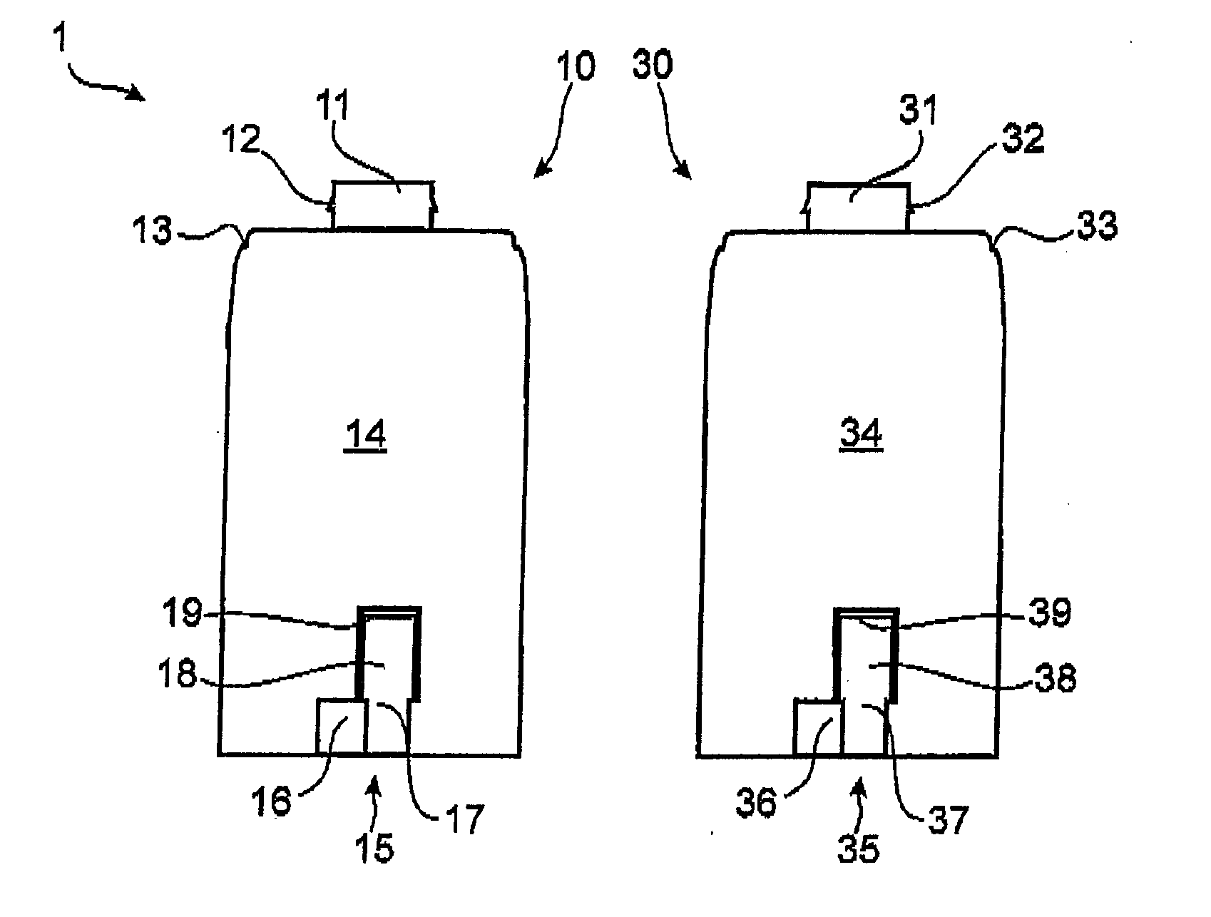
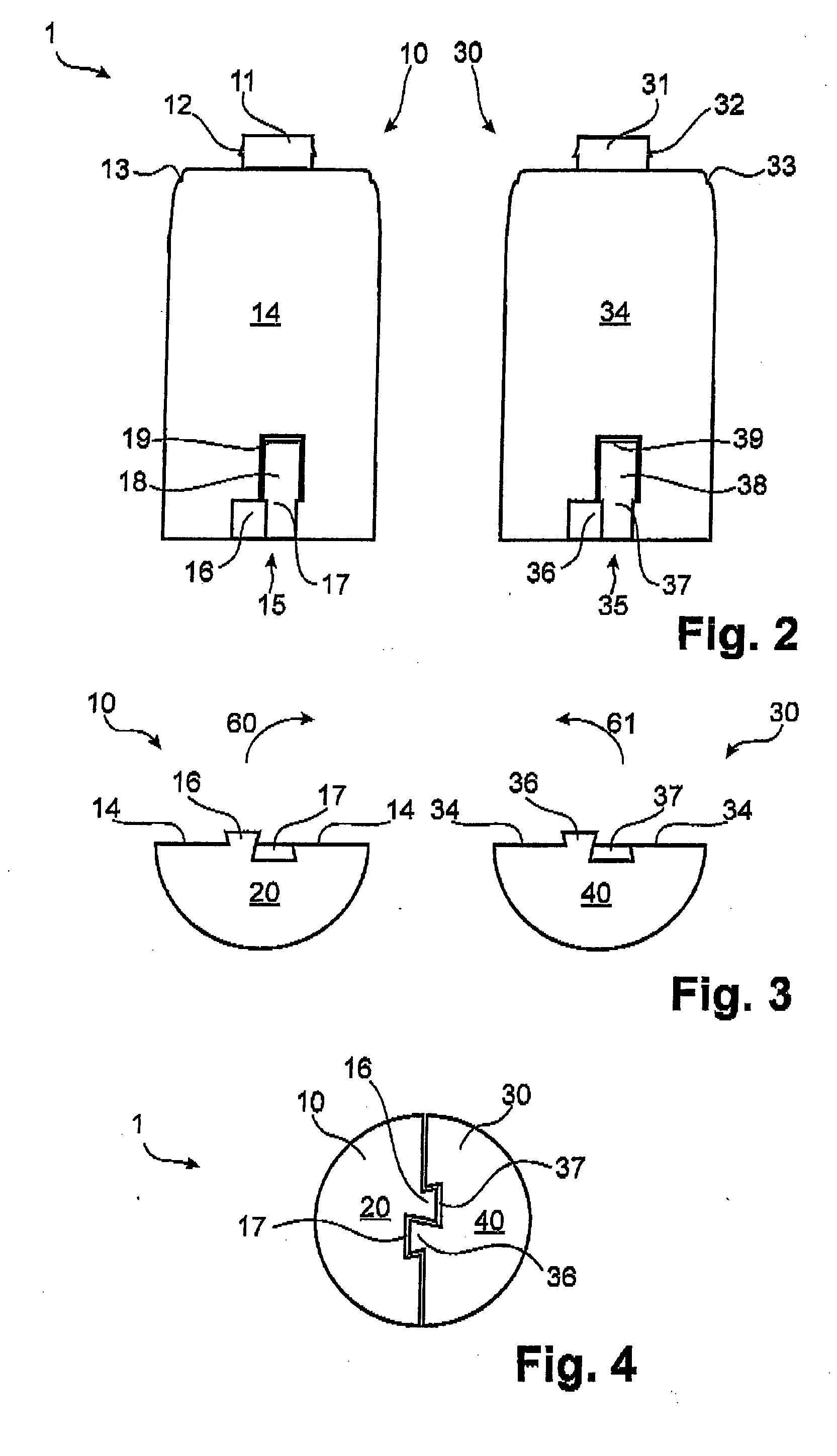
[0008] According to one embodiment, the containers that can be combined to form the reservoir each have at least one engagement element in the area facing the bottom side of the container. Each engagement element comprises at least one projecting element and at least one corresponding recessed element. The engagement element of each container interacts with the engagement element of the other container so that the at least two containers can be combined to form the reservoir by inserting the projecting elements of each container into the recessed elements of the respectively other container. This configuration of the anchoring on the contact surfaces of the two containers with the aid of the protuberant, protruding or projecting element and the corresponding recessed element connects the containers to form a reservoir in a positive locking and stable manner. At the same time, the containers are nevertheless readily detachable.
[0009] Since, in one embodiment, the containers are fastened only in a partial area and not over the entire container length or height, they can easily be connected to form the reservoir. Because the
interconnection is provided in the area of the reservoir that is most remote from the pump and dosing unit, the overall stability of the dosing dispenser is at the same time substantially increased. A shifting of the containers, e.g., due to lateral pressure, is inhibited because the containers and thus the reservoir are interconnected to form a unit not only by the dosing device but also by the engagement elements. This positive locking anchoring can also be described as a
tongue and groove joint or a bayonet joint. Likewise, the protruding element could also be described as a latching projection.
[0010] In addition to affording the
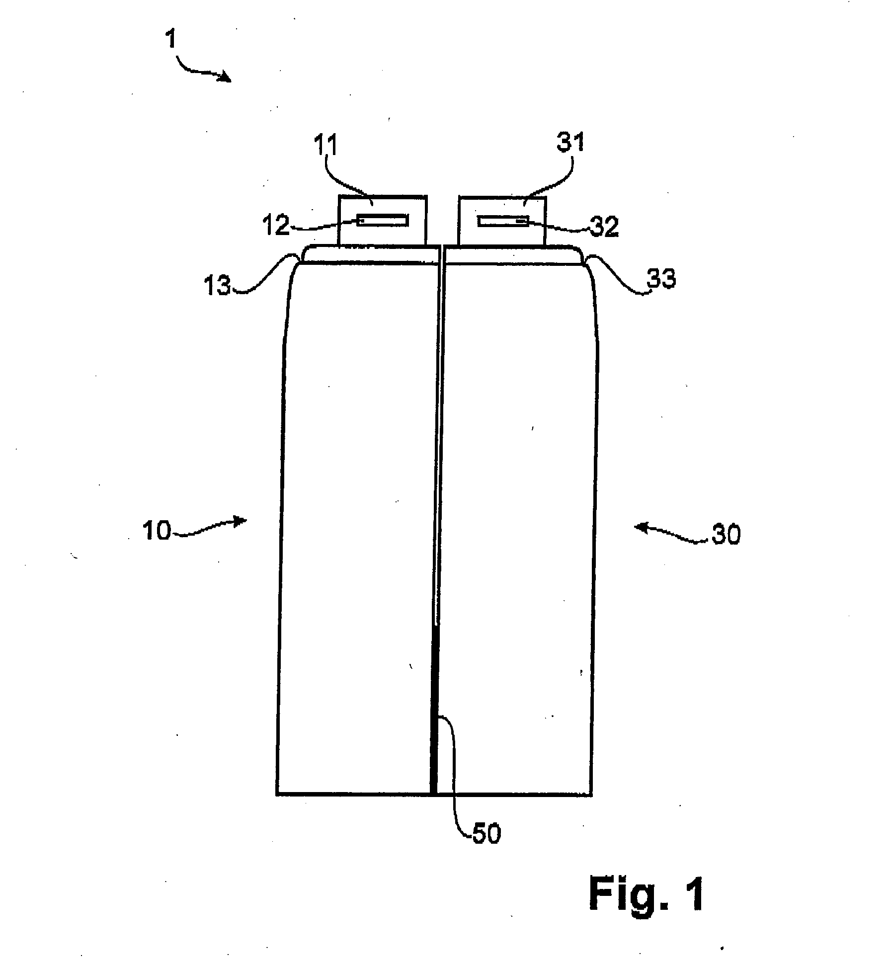
advantage of simple yet secure combinability of the two containers, there are other advantages as well. Because of the manner in which the engagement elements are arranged on the contact surfaces of the containers according to the invention, it is sufficient to produce only a single container type, which based on the opposite connection is then complemented in
mirror image. For example, if only one indentation were provided on one container and only one protruding element on the other, two different containers and molds would have to be produced to manufacture the reservoir according to the invention and thus the dosing dispenser. This would increase the production costs considerably. However, because one complete engagement element comprises a protruding element and a corresponding recessed element is provided on each container, it is sufficient to provide only a single container type, two (or more) of which can be connected to form a reservoir. This significantly reduces the production costs for a dosing dispenser and a reservoir according to the invention.
[0013] In one embodiment, the engagement elements are centered relative to the
vertical axis of the container. Even an eccentric arrangement, however, does not impair the effect and function of the engagement elements according to the invention. Furthermore, at least the recessed elements—and in this case also the protruding elements—of the engagement element can extend over the entire container height. This would achieve an even more stable engagement of the two containers, i.e., it would further improve the stability of the anchoring.
[0014] In one embodiment, the reservoir according to the invention is made of a plastic material, which is can be formed by
blow molding. Especially when the
blow molding process is used, it is important that the reservoirs produced can be easily removed from the mold, without the mold having to be disassembled into many individual parts or long mold slides having to be provided to remove the reservoirs from the mold. This is ensured specifically by the configuration of the engagement elements according to the invention and the reservoirs per se. As a result the mold is compact and simple. In addition, the
production cycle times are reduced. This, too, lowers the production costs for the reservoirs and thus for the dosing dispenser as a whole. This, however, is a prerequisite for the dosing dispenser to be used in a wide range of applications, e.g., in
cosmetics.

