Steering wheel assembly

a technology for steering wheels and airbags, which is applied in the directions of transportation and packaging, vehicular safety arrangements, pedestrian/occupant safety arrangements, etc., can solve the problems of increasing the overall production cost of manufacturers, triggering the airbag inflator, and injuring passengers, so as to improve the visual appearance and feel of the steering wheel

Active Publication Date: 2005-01-20
AUTOLIV ASP INC
View PDF19 Cites 19 Cited by
  • Summary
  • Abstract
  • Description
  • Claims
  • Application Information

AI Technical Summary

Benefits of technology

[0018] The present invention has been developed in response to the present state of the art, and in particular, in response to problems and needs in the art that have not yet been fully solved by currently available steering wheels. The steering wheel of the present invention comprises a center portion and an outer rim. The outer rim encircles the center portion. As the outer rim may not be attractive to a vehicle occupant, a coating may be added to cover the outer rim and improve the visual appearance and feel of the steering wheel.
[0020] The steering wheel further comprises an airbag cover that goes over the top of the center portion. The cover forms the upper boundary of the center portion and, like the coating, is designed to improve the visual appearance of the steering wheel. Preferably, the cover forms an interface with the intermediate portion
[0025] The steering wheel is further designed such that when the steering wheel is in the normal position, there is no gap at the interface between the cover and the intermediate portion. In one embodiment, this is accomplished by constructing the intermediate portion to include an overhanging portion. The overhanging portion is positioned at the interface between the intermediate portion and the cover and is designed to overlap the cover. Preferably, the overhanging portion fits tightly with the cover and prevents a gap from forming at the interface between the intermediate portion and the cover when the upper housing is in the normal position.
[0029] In this embodiment, depressing the upper housing from the normal position into the compressed position does not produce a gap at the interface between the cover and the intermediate portion. Rather, when the vehicle occupant presses inwardly on the cover, the flex point allows the cover and / or the shingle to move and / or bend to compensate for the movement of the upper housing. As a result, even when the upper housing is in the compressed position, there is no gap formed at the interface between the cover and the intermediate portion.

Problems solved by technology

If the airbag cover were allowed to detach and freely move into the passenger compartment, it could cause injury to a passenger.
If this accelerometer measures an abnormal deceleration, such as one caused by a collision event, it triggers the airbag inflator.
Unfortunately, constructing a steering wheel such that there is a gap positioned between the airbag module and the other portions of the steering wheel significantly raises the manufacturer's overall production costs.
By requiring a gap to surround the airbag module, the overall complexity and sophistication of the steering wheel is greatly increased.
The significance of such a cost increase cannot be over-emphasized because in the highly competitive automobile industry, even slight increases in production costs can greatly influence the overall profit margin on a mass-produced vehicle.
Moreover, including a gap on a steering wheel has a further limitation in that over the life of the vehicle, containments such as dirt, dust, moisture, and the like tend to collect and accumulate within the steering wheel gap.
This accumulation of dirt makes the steering wheel undesirable and visually unappealing to most consumers.
As a result, the overall satisfaction and enjoyment associated with driving and / or owning the vehicle will be greatly diminished.
Like the accumulation of dirt discussed above, such poking will, over time, deteriorate the visual appearance of the steering wheel and reduce the vehicle's overall desirability.

Method used


Image

  • Steering wheel assembly
  • Steering wheel assembly
  • Steering wheel assembly

Examples


Embodiment Construction

[0037] The preferred embodiments of the invention are now described with reference to FIGS. 1-5, wherein like parts are designated by like numerals throughout. The members of the present invention, as generally described and illustrated in the Figures, may be constructed in a wide variety of configurations. Thus, the following more detailed description of the embodiments of the present invention, as represented in the Figures, is not intended to limit the scope of the invention, as claimed, but is merely representative of presently preferred embodiments of the invention.

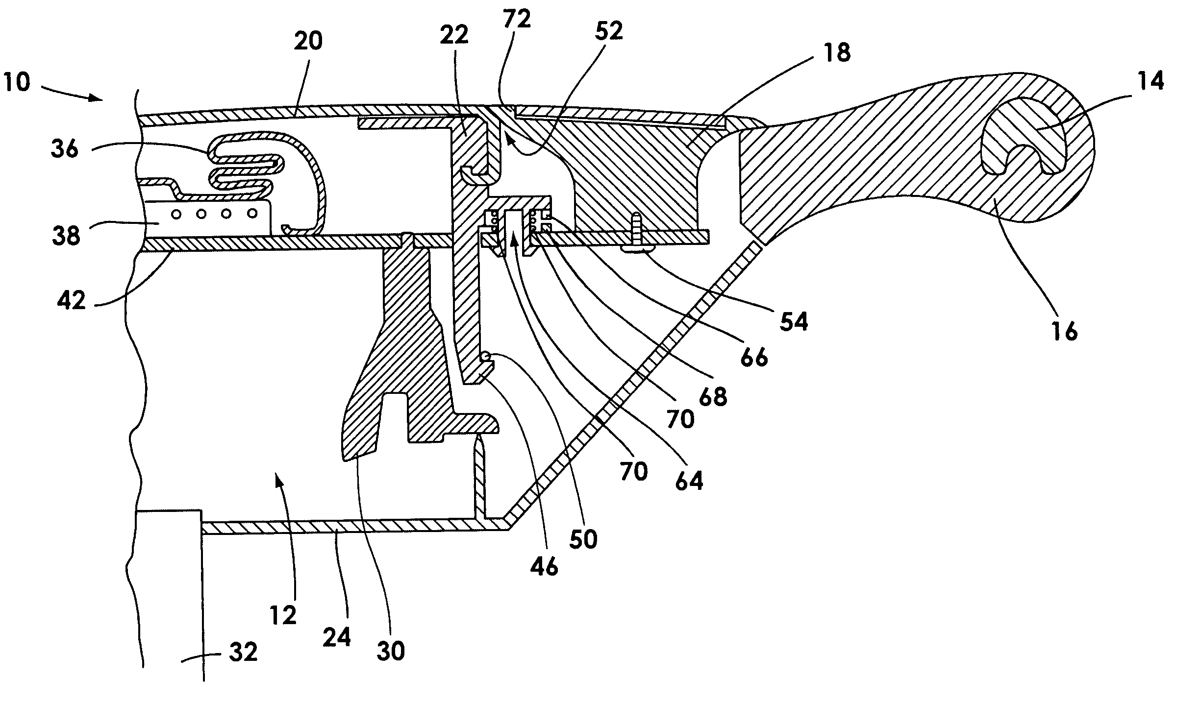
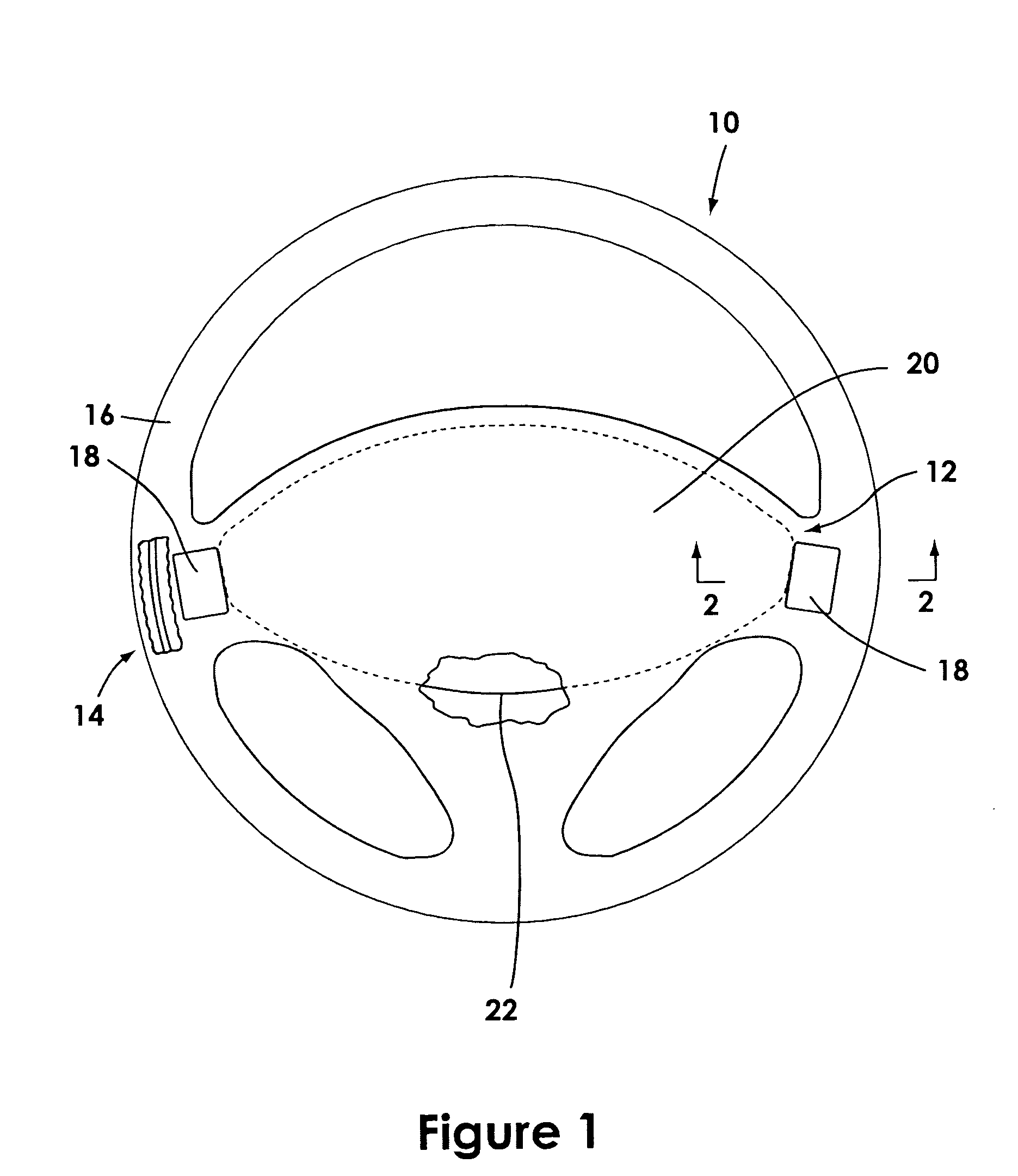
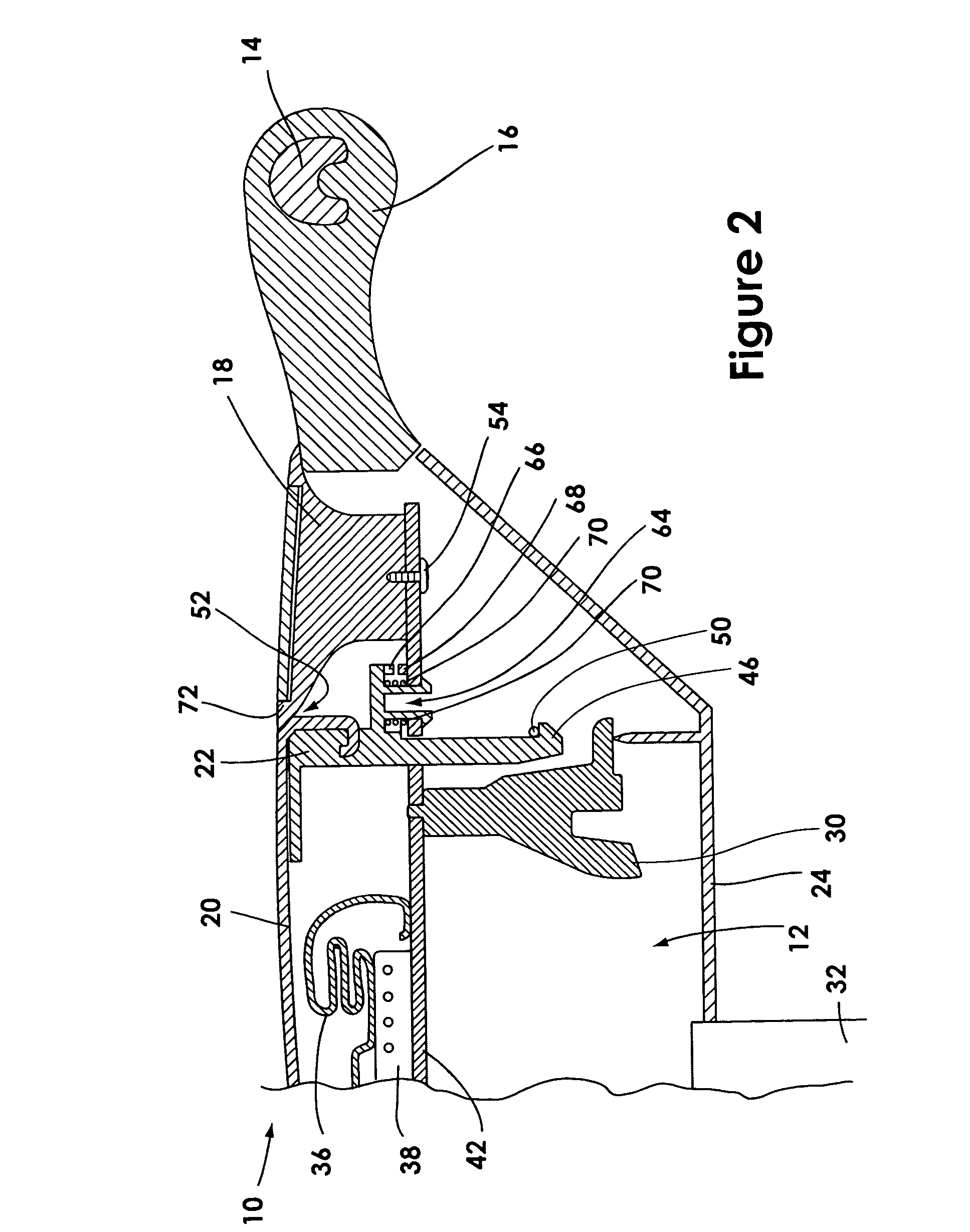
[0038] Referring now to FIG. 1, a front plan view of a steering wheel 10 of the present invention is depicted. The steering wheel 10 may be mounted in a vehicle (not shown). In general, the steering wheel 10 comprises a center portion 12 and an outer rim 14. The outer rim 14 encircles the center portion 12 and is generally made of metal such as steel, aluminum, magnesium, and the like. A coating 16 of polyurethane, ...


PUM


Abstract

The present invention relates to a steering wheel assembly. The steering wheel assembly has a center portion and an outer rim. The outer rim encircles the center portion. A cover and an upper housing are also added to the center portion. The cover goes over the top of the center portion whereas the upper housing is positioned below the cover. The upper housing is constructed such that it is capable of being depressed from a normal position to a compressed position. An intermediate portion is also added to the steering wheel. The intermediate portion is positioned between the outer rim and the center portion and forms an interface with the cover. The steering wheel is constructed such that when the upper housing is in the normal position, there is no gap at the interface between the cover and the intermediate portion. This may be accomplished by constructing the intermediate portion to include an overhanging portion that overlaps and fits together with the cover. Alternatively, a shingle that attaches the cover to the intermediate portion may be used to prevent a gap from forming at the interface when the upper housing is in the normal position.

Description

BACKGROUND OF THE INVENTION [0001] 1. Field of the Invention [0002] The present invention relates to steering wheel and airbag assemblies, as well as their interfaces on motor vehicles. More specifically, the invention relates to a novel steering wheel and airbag assembly that eliminates the gap between the driver's side airbag cover and the steering wheel. [0003] 2. Description of Related Art [0004] Steering wheels are universally used as an essential component of a motor vehicle. Through the steering wheel, the vehicle driver steers and controls the vehicle. The steering wheel controls the vehicle's steering assembly such that the vehicle driver is able to control the vehicle's movement and direction by simply rotating the steering wheel. [0005] Traditionally, a steering wheel includes two sections: a center portion (often called a “center” or a “body”) that is coupled to an outer rim (sometimes called a “rim”). The outer rim encircles the center portion and is designed to receive...

Claims


Application Information

Patent Timeline
Patent Type & Authority Applications(United States)
IPC IPC(8): B60Q5/00B60R21/20B60R21/203B60R21/215
CPCB60Q5/003B60R21/21658B60R21/2037
Inventor RHEA, SCOTT L.
Owner AUTOLIV ASP INC
Why Eureka
Try Eureka