Robotic pen

a robot pen and pen body technology, applied in the field of manufacturing and repairing of objects, can solve the problems of limiting the ability to place the thermocouples where desired, and it is difficult if not impossible to disperse the material stream

Active Publication Date: 2005-01-20
GENERAL ELECTRIC CO
View PDF19 Cites 82 Cited by
  • Summary
  • Abstract
  • Description
  • Claims
  • Application Information

AI Technical Summary

Problems solved by technology

However, if the part has a complex 3D configuration with varying curvature, it is difficult if not impossible to dispense the material stream along the curved surfaces thereof, and therefore relatively flat portions of the part must be used instead.
This limits the ability to place the thermocouples where desired.

Method used


Image

  • Robotic pen
  • Robotic pen
  • Robotic pen

Examples


Embodiment Construction

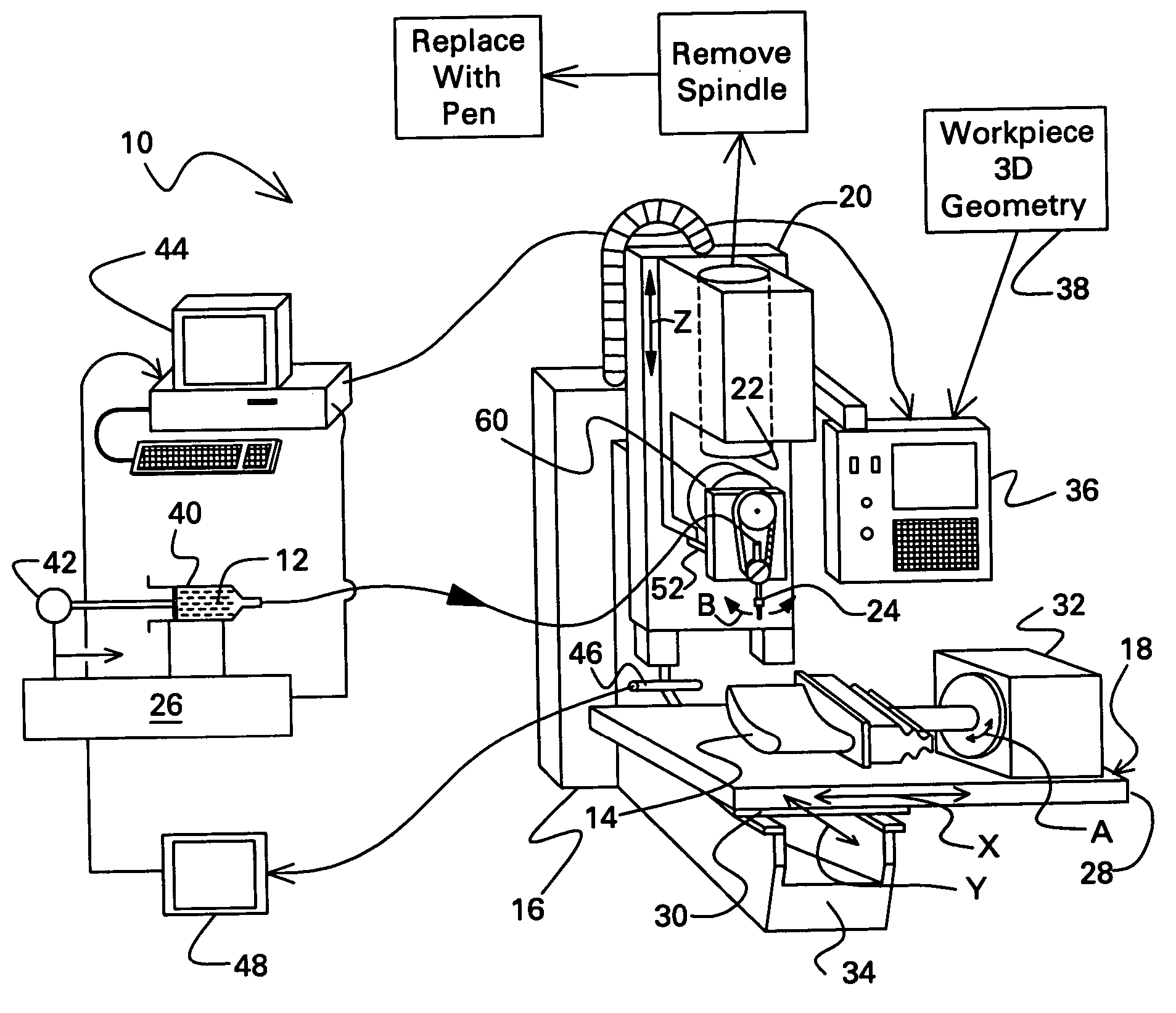
[0012] Illustrated schematically in FIG. 1 is a robotic pen 10 specifically configured for dispensing or writing any suitable material 12 in a stream atop the surface of any suitable workpiece 14. In particular, the workpiece may have a simple 2D configuration such as a flat plate, yet more commonly will have a complex 3D configuration with varying curvature or change in contour along its three axes.

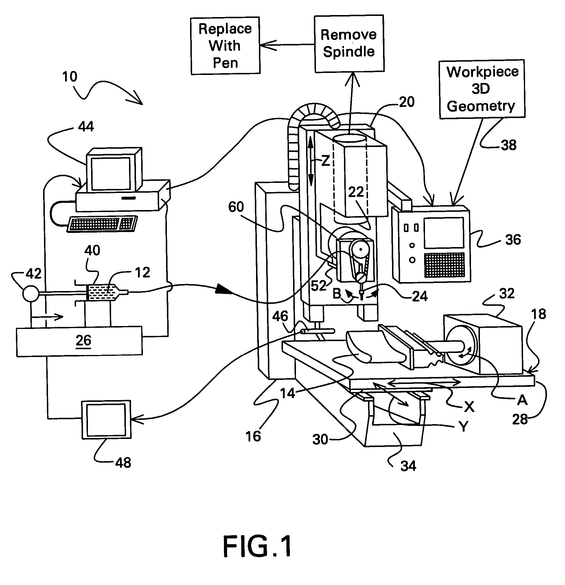
[0013] The exemplary workpiece 14 is illustrated in FIG. 2 in more detail in the form of a turbine blade including an arcuate airfoil having a generally concave pressure side and generally convex opposite suction side extending outwardly from a flat platform having a typical retention dovetail therebelow.

[0014] The robotic pen illustrated in FIG. 1 is an assembly of primarily conventional components suitably modified in a collective apparatus or system for writing with precision on the various surfaces of the 3D workpiece 14 for any suitable purpose, such as original manufacture, repai...


PUM

PropertyMeasurementUnit
relative movementaaaaaaaaaa
movementaaaaaaaaaa
temperatureaaaaaaaaaa

Abstract

A robotic pen includes a computer numerically controlled machine having a multiaxis stage for mounting a workpiece, and a cooperating elevator which translates relative thereto. A pen tip is rotatably mounted to the elevator. And, a dispenser is joined in flow communication with the pen tip for ejecting a stream of material atop the workpiece as the workpiece moves relative thereto for maintaining a substantially constant gap between said pen tip and the workpiece during relative movement therebetween.

Description

BACKGROUND OF THE INVENTION [0001] The present invention relates generally to manufacturing and repairing of articles, and, more specifically, to dispensing or writing a material stream in desired patterns. [0002] Manufactured parts or workpieces are found in myriad configurations from simple two-dimensional (2D) flat plates to complex bodies varying in curvature or contour in three dimensions (3D). Correspondingly, various types of machines are available for the manufacture and repair thereof including simple single-axis machines to complex multiaxis computer numerically controlled (CNC) machines. [0003] These various machines typically remove material by cutting, whereas other machine add material by welding, brazing, or deposition. In one form of material deposition, a line or stream of material is deposited or written on a flat surface in predetermined patterns from simple lines to complex grids. [0004] In one commercially available apparatus, a flat substrate, such as an electr...

Claims


Application Information

Patent Timeline
Patent Type & Authority Applications(United States)
IPC IPC(8): B05B13/04B05C5/02B43K8/00B43K8/22B44B1/00
CPCB05B13/0431B05C5/0216B43K8/00G05B2219/49231B44B1/006G05B2219/37212G05B2219/37215B43K8/22
Inventor RUTKOWSKI, STEPHEN FRANCISHARDWICKE, CANAN USLUGIGLIOTTI, MICHAEL FRANCIS XAVIERJACKSON, MELVIN ROBERT
Owner GENERAL ELECTRIC CO
Why Eureka
Try Eureka