Golf iron

a golf iron and iron plate technology, applied in the field of golf clubs, can solve the problems of reducing the accuracy of the iron plate,

Inactive Publication Date: 2005-01-20
AMERICAN SPORTS LICENSING
View PDF18 Cites 249 Cited by
  • Summary
  • Abstract
  • Description
  • Claims
  • Application Information

AI Technical Summary

Benefits of technology

[0008] According to another embodiment of the invention a set of golf clubs is provided. Each of the golf clubs in the set includes a shaft and a club head. Each club head includes a hosel for connecting the club head to the shaft, a striking surface, and a rear portion opposite the striking surface. At least one of the lower lofted clubs and at least one of the higher lofted clubs in the set each includes a muscle back portion as an element of the rear portion and defining a cavity in the muscle back portion. The cavity of the at least one lower lofted club is larger in volume than the cavity of the at least one higher lofted club.
[0009] According to yet another embodiment of the invention, a golf club is provided. The golf club includes a shaft and a muscle back iron golf club head attached to the shaft. The muscle back head includes a substantially flat back having an extra mass portion positioned toward the bottom of the club head, wherein the extra mass portion defines a cavity therein. The cavity can be substantially entirely enclosed within the club head. The cavity can be filled with a high rebound elastomer. A substantial portion to the extra mass can be positioned below the cavity.

Problems solved by technology

Muscle back irons, however, are neutral in concentration of mass in a lateral direction, providing no corrective bias to a ball struck near the, heel or the toe of the golf club head.
Draws and fades are more difficult to achieve using perimeter weighted clubs because it requires the golfer to work against the corrective features built into the cavity back club.

Method used


Image

  • Golf iron
  • Golf iron
  • Golf iron

Examples


Embodiment Construction

[0015] The detailed embodiments of the present invention are disclosed herein. It should be understood, however, that the disclosed embodiments are merely exemplary of the invention, which may be embodied in various forms. Therefore, the details disclosed herein are not to be interpreted as limited, but merely as the basis for the claims and as a basis for teaching one skilled in the art how to make and / or use the invention.

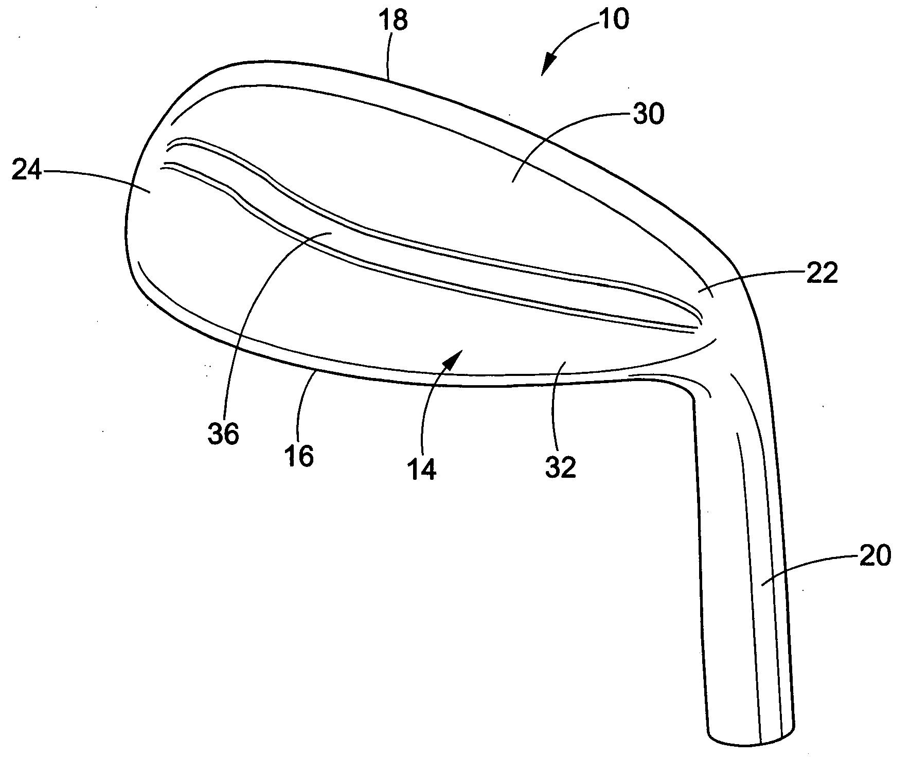
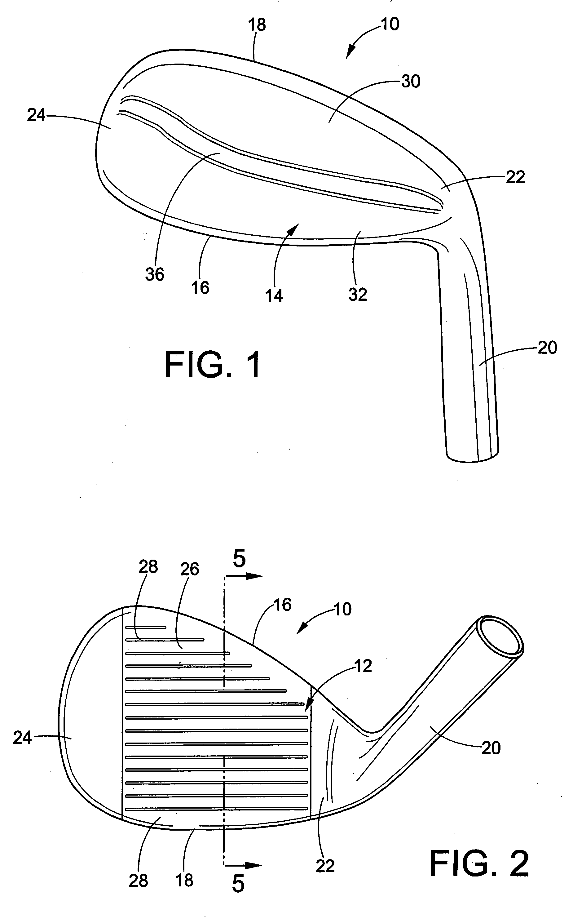
[0016] With reference to FIGS. 1 and 2, a golf club head 10 includes a front surface 12, a rear surface 14, a top edge 16, a sole 18, and a hosel 20. The golf club head includes a heel portion 22 near the hosel and a toe portion 24 towards an end opposite the heel portion. The front surface defines a striking face 26. Scores or grooves 28 are formed in the striking face. The striking face can comprise a strike face insert (not shown) that is received in the club head. If the club head uses a strike face insert, the insert can be made of a different material than...


PUM


Abstract

A golf club head includes a front surface, a rear surface, a sole, a top edge, a hosel, and a muscle back portion. The front surface defines a strike face. The rear surface is opposite the front surface. The muscle back portion is interposed between the front surface and the rear surface and defines a cavity disposed in the muscle back portion. An elastomer can at least partially fill the cavity.

Description

BACKGROUND OF THE INVENTION [0001] This invention relates to golf clubs. More particularly, this invention relates to golf club irons. The invention is particularly useful for muscle back iron golf club heads. [0002] Iron golf club heads are generally available in three different styles: the blade, the muscle back, and the cavity back. Hybrids of the three different styles are also available. The blade type iron has a club head where the back is substantially flat. In contrast, the muscle back iron positions extra mass toward the bottom half of the back of the club head. The cavity back positions mass around the entire back periphery of the club head. [0003] When struck, a golf ball is most strongly influenced by an area of concentrated mass closest to where the ball strikes the face. Muscle back irons concentrate mass towards the bottom half of the head and therefore help the golf ball get airborne. Muscle back irons, however, are neutral in concentration of mass in a lateral direc...

Claims


Application Information

Patent Timeline
Patent Type & Authority Applications(United States)
IPC IPC(8): A63B53/00
CPCA63B53/0475A63B2053/042A63B53/047A63B2053/005A63B53/005A63B53/042
Inventor LEE, MICHAEL
Owner AMERICAN SPORTS LICENSING
Why Eureka
Try Eureka