
Analysis of causal relations between intercommunicating nodes

a causal relationship and intercommunicating node technology, applied in the field of analyzing the relationships between messages sent, can solve the problems of difficult debugging of distributed systems, difficult diagnosis of performance issues in distributed systems, and different components' source cod

Inactive Publication Date: 2005-01-20
HEWLETT PACKARD DEV CO LP
View PDF4 Cites 18 Cited by
  • Summary
  • Abstract
  • Description
  • Claims
  • Application Information

AI Technical Summary

Benefits of technology

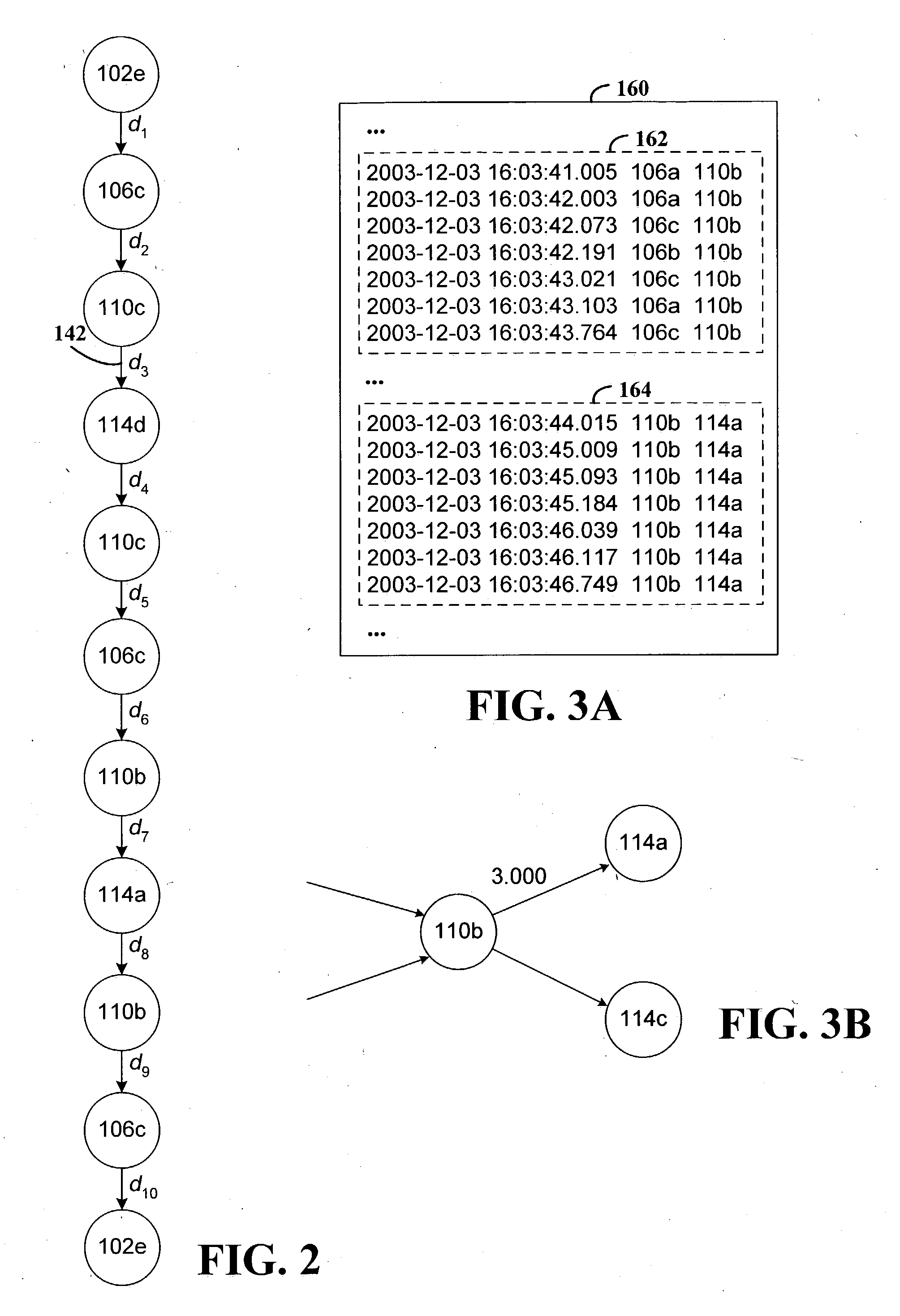
The various embodiments of the invention support determining causal relations between a plurality of intercommunicating nodes. Communications between the nodes may be described by input trace data. The trace data may include for each message sent between nodes a timestamp that indicates a time at which the message was sent, a source identifier that identifies a node from which the message was sent, and a destination identifier that identifies a node to which the message was sent. For each of one or more no

Problems solved by technology

Distributed systems can be difficult to debug, especially when users experience poor performance.
Diagnosing performance issues is even more difficult in distributed systems if the constituent components are composed of “black-box” components.
For example, some distributed systems may be constructed from software from many different, and perhaps competing, vendors, and the source code of the different components may be unavailable.
Without more than a high-level understanding of the functions provided by the various components, and without the information that could be learned from examination of the source code, selecting a component to begin investigating may involve guesswork and result in wasted time.
The business model under which distributed systems are sold and deployed also contributes to the difficulties associated with addressing performance problems.
While modestly-skilled programmers can design and construct such systems, they may lack the expertise to debug performance problems efficiently.
Vendors of individual components may provide training and support for solving performance problems within the components, but not necessarily support for solving performance problems when components from other vendors are involved.
Thus, whole-system performance debugging may require either an inordinate amount of time or the services of expensive and hard-to-find systems integration experts.

Method used


Image

  • Analysis of causal relations between intercommunicating nodes
  • Analysis of causal relations between intercommunicating nodes
  • Analysis of causal relations between intercommunicating nodes

Examples


Embodiment Construction

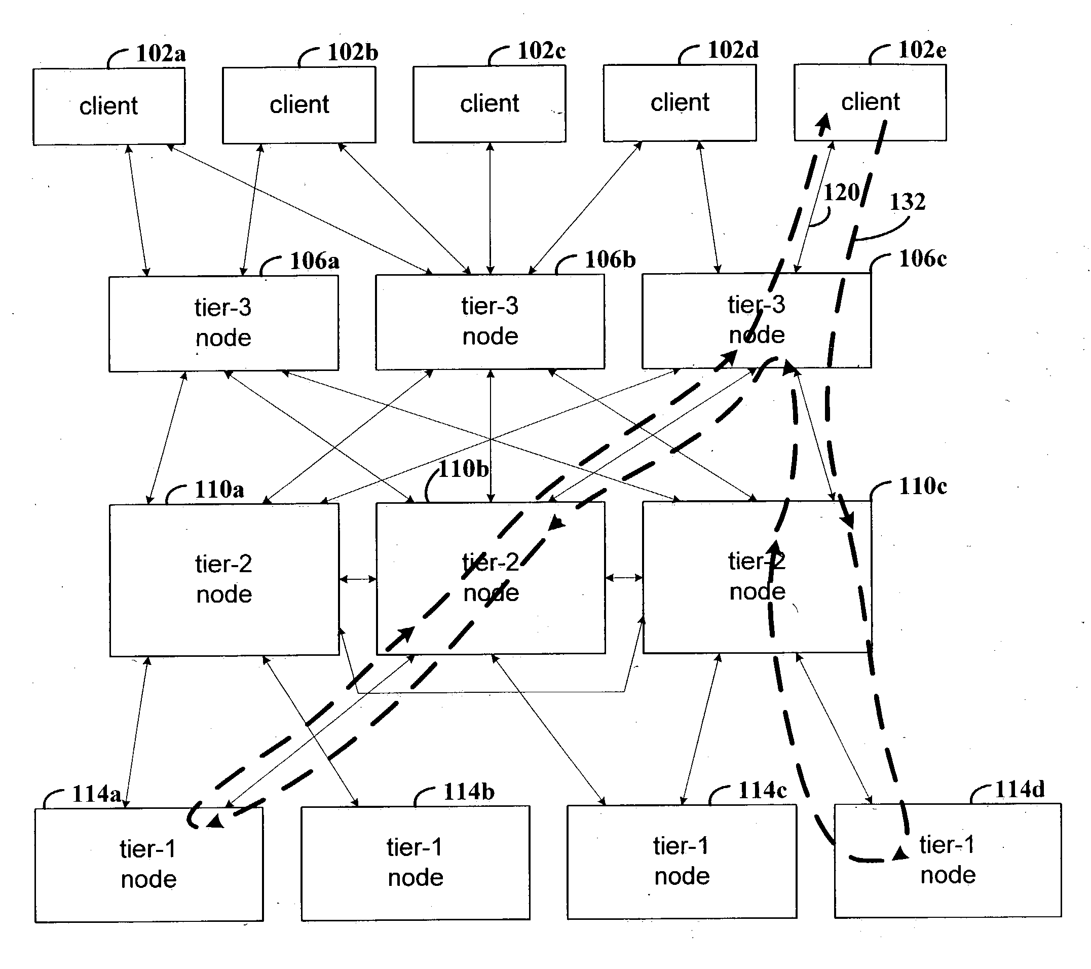
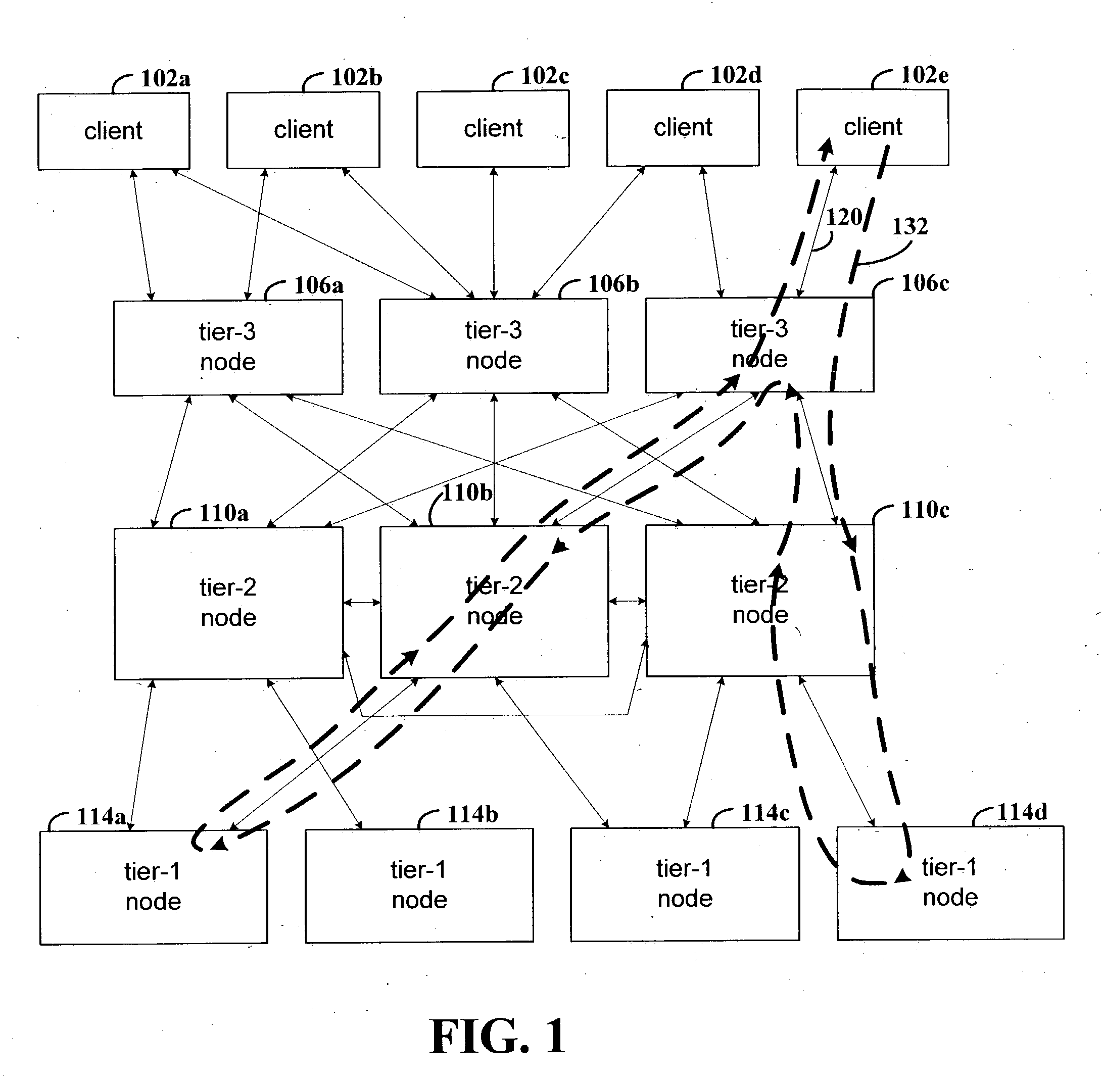
The various embodiments described herein infer causal relations of messages sent between nodes, where the causal relations may assist in locating performance problems. The nodes may represent host computer systems in a distributed data processing arrangement, computer processes, threads, active objects, disk drives or various combinations thereof. The inner functions of the constituent nodes need not be apparent to infer the causal relations. The nodes and communication relationships may be represented as a graph, with vertices in the graph representing the nodes and edges between the vertices representing communications between the nodes.

The causal relations may be inferred from traced communication information. The nodes may be determined from the traced communication information and may be represented as vertices in a graph. An edge may be added to the graph to connect two vertices that represent nodes that communicate, as indicated by the traced communication information. A c...


PUM


Abstract

Method and apparatus for determining causal relations between a plurality of intercommunicating nodes. In various embodiments, trace data is input that describe inter-node communication. The trace data may include for each message sent between nodes a timestamp that indicates a time at which the message was sent, a source identifier that identifies a node from which the message was sent, and a destination identifier that identifies a node to which the message was sent. For each of one or more nodes, a determination may be made as to whether one or more causal relations exist between a first set of messages destined to the node and a second set of messages sourced from the node and destined to at least one other node. A causal relation may exist as a function of a probability distribution of delay values that are differences between timestamps of messages in the second set and timestamps of messages in the first set. From the nodes and causal relations a processor-readable representation is generated.

Description

FIELD OF THE INVENTION The present disclosure generally relates to analyzing the relationships between messages sent between nodes. BACKGROUND Many commercially-important systems, especially Web-based applications, are composed of a number of communicating components. These systems are often structured as distributed systems, with components running on different processors or in different processes. For example, a multi-tiered system may process requests from Web clients that flow through a Web-server front-end and then to a Web application server. The application server may then call a database server, for example, or other types of services such as for authentication, name service, credit-card authorization, or customer relationship management or other support functions. Distributed systems can be difficult to debug, especially when users experience poor performance. Diagnosing performance issues is even more difficult in distributed systems if the constituent components are co...

Claims


Application Information

Patent Timeline
IPC IPC(8): G06F15/16H04L12/24
CPCH04L41/00H04L12/24
Inventor AGUILERA, MARCOS KAWAZOEMOGUL, JEFFREY CLIFFORD
Owner HEWLETT PACKARD DEV CO LP
Learn More