Anchoring clamp

a clamp and anchoring technology, applied in the direction of snap fasteners, buckles, mechanical devices, etc., can solve the problems of difficult positioning between locked and unlocked attitudes, aircraft damage, etc., and achieve the effect of convenient manipulation and operation, improved locking capabilities, and large surface to surface conta

Inactive Publication Date: 2005-01-27
STAFFORD JEFFREY B
View PDF11 Cites 35 Cited by
  • Summary
  • Abstract
  • Description
  • Claims
  • Application Information

AI Technical Summary

Benefits of technology

[0004] With the foregoing in mind, it is an object of the present invention to provide a clamp particularly adapted for securing tie-down lines, securing aircraft to the tarmac in a parked position. The clamp of the present invention is characterized by novel features of construction and arrangement which makes it easy to manipulate and operate the clamp between an open position permitting adjustment of lines and a locked position securing the lines. It has been found that the novel locking arrangement secures the lines firmly in a non-slip fashion which is an important consideration in securing small aircraft at airports. Thus the clamp comprises an elongated body portion which is offset angularly at its upper end and has a bore extending through the body portion which in the present instance is of circular cross-section and generally of a diameter greater than the diameter of a cable or cord which passes through the bore of the clamp. The body portion typically has a hook, in the present which may be formed integrally therewith for attaching the clamp to a suitable fitting such as a hook or ring on an aircraft part, such as a wing. A clamping screw, having a threaded shank which engages an internally threaded boss on the side wall of the body portion of the clamp mounts a shoe having an arcuate face which is generally of the same contour as the cable to provide a large surface to surface contact and better locking capabilities. The bore has a recess confronting the shoe so that the cable is deflected into the recess when the screw moves the shoe to a locking position.

Problems solved by technology

It has been found that some of them are difficult to position between locked and unlocked attitudes.
Other tie-down clamps for aircraft have exhibited a tendency to loosen when wind conditions are severe which is some instances results in damage to the aircraft.

Method used


Image

  • Anchoring clamp
  • Anchoring clamp
  • Anchoring clamp

Examples


Embodiment Construction

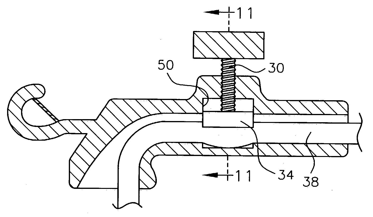
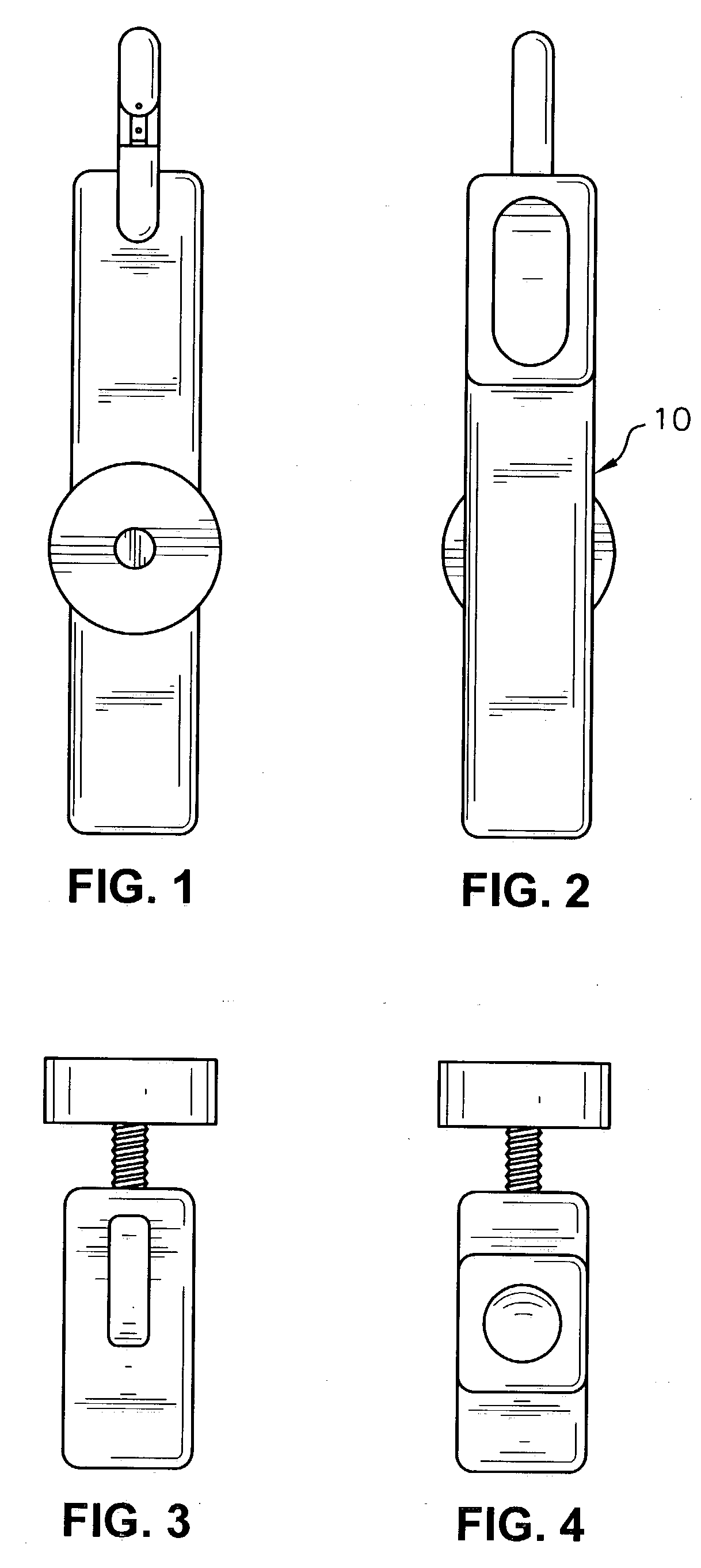
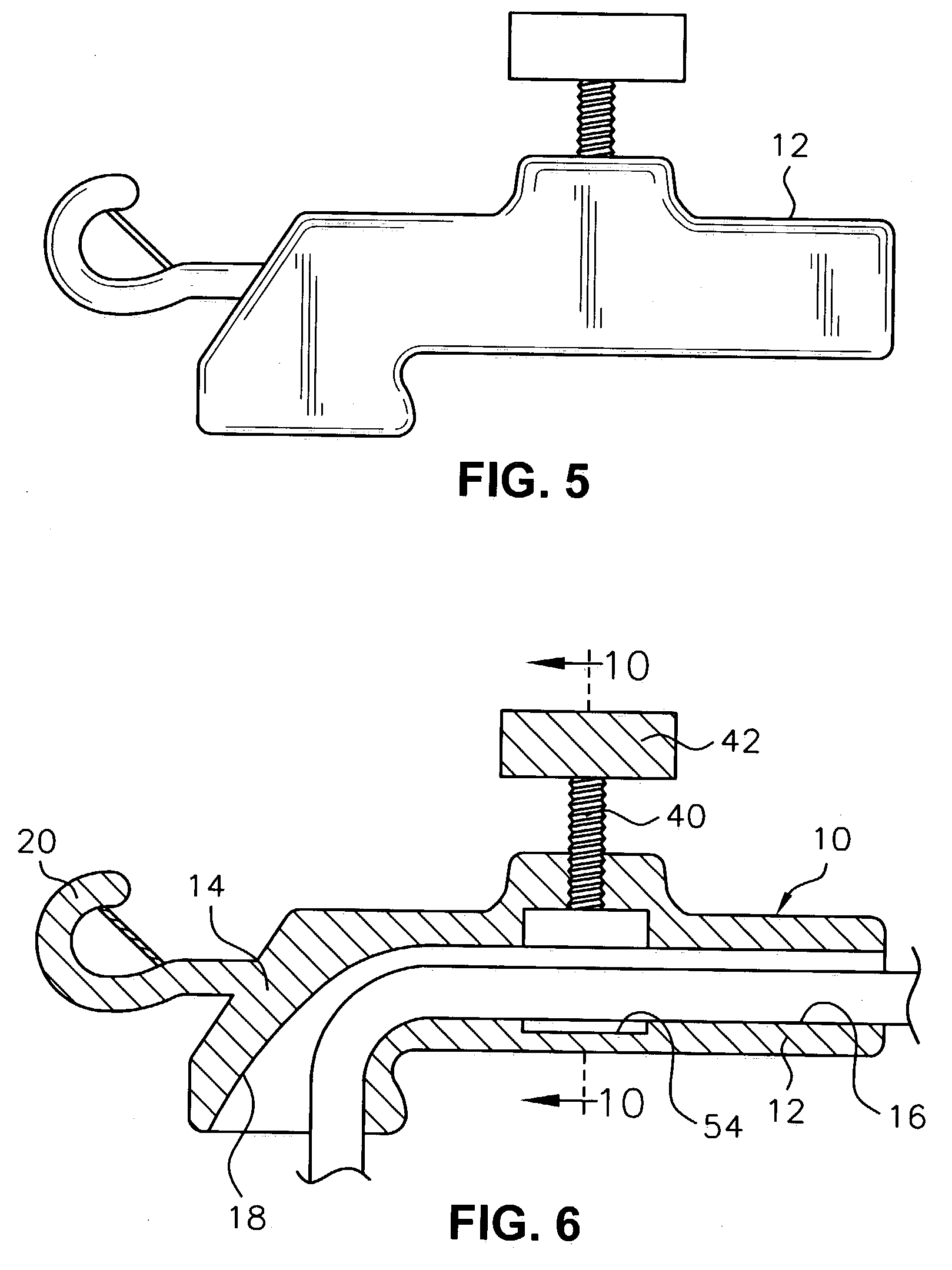
[0016] Referring now to the drawings and particularly to FIG. 10 thereof, there is shown a clamp assembly in accordance with the present invention generally designated by the numeral 10. The clamp has many applications and is illustrated herein as the primary means for securing the lines of an aircraft on a tarmac. The clamp of the present invention is easy to manipulate and operate between an open position permitting adjustment of lines and a locked position and by reason of the novel locking arrangement secures the lines firmly which is an important consideration in securing small aircraft at airports. It has been found that high winds tend to buffet the aircraft and loosen lines where they are simply tied by knots or the like as is presently the tie-down procedure

[0017] The clamp assembly 10 comprises an elongated body portion 12, in the present instance, of generally square cross section having an offset upper portion as at 14. The body portion 12 has a centrally located bore 1...


PUM


Abstract

A clamp assembly for securing a flexible cable comprising an elongated body portion, a bore extending through the body portion, a clamping screw mounted in a sidewall of the body portion mounting a shoe at its inner end which snugly fits in a pocket, said shoe having an arcuate face to snugly embrace the cable and a means to finding a recess in the bore wall located opposite said show whereby rotation of screw in direction to advance the shoe inwardly presses the cable into the recess to firmly lock it in place.

Description

[0001] This application claims the benefit of U.S. Provisional Application No. 60 / 393,535 filed Jul. 2, 2002.FIELD OF THE INVENTION [0002] The present invention relates broadly to clamping devices and more specifically a clamp for anchoring small aircraft in a park position on the tarmac. BACKGROUND OF THE INVENTION [0003] Clamps of the type to which the present invention relates are not new per se. The prior art clamps have certain disadvantages and draw backs. It has been found that some of them are difficult to position between locked and unlocked attitudes. Other tie-down clamps for aircraft have exhibited a tendency to loosen when wind conditions are severe which is some instances results in damage to the aircraft. SUMMARY OF THE INVENTION [0004] With the foregoing in mind, it is an object of the present invention to provide a clamp particularly adapted for securing tie-down lines, securing aircraft to the tarmac in a parked position. The clamp of the present invention is chara...

Claims


Application Information

Patent Timeline
Patent Type & Authority Applications(United States)
IPC IPC(8): B64F1/16F16G11/00
CPCB64F1/16Y10T24/3958Y10T24/3967F16G11/00F16G11/06F16G11/143
Inventor STAFFORD, JEFFREY B.
Owner STAFFORD JEFFREY B
Why Eureka
Try Eureka