Modular automatic spray gun manifold

a spray gun and module technology, applied in the direction of dental surgery, combustion types, lighting and heating apparatuses, etc., can solve the problems of difficult cleaning, difficult mounting of the manifold in cantilever fashion, and difficult manifold installation, so as to facilitate mounting and manipulation

Active Publication Date: 2007-02-08
SPRAYING SYST
View PDF5 Cites 10 Cited by
  • Summary
  • Abstract
  • Description
  • Claims
  • Application Information

AI Technical Summary

Benefits of technology

[0005] Accordingly, in view of the foregoing, an object of the present invention is to provide an improved lightweight spray gun manifold adapted for easier mounting and manipulation.

Problems solved by technology

The size and weight of these manifold supports makes it difficult to mount the manifold in cantilever fashion, such as from a pivot door of a pill coating machine and to manipulate the manifold as may be required during use and / or cleaning.
This type of manifold not only requires extensive plumbing, but it is also difficult to clean, particularly to the extent required for use in pharmaceutical and food applications.

Method used


Image

  • Modular automatic spray gun manifold
  • Modular automatic spray gun manifold
  • Modular automatic spray gun manifold

Examples


Embodiment Construction

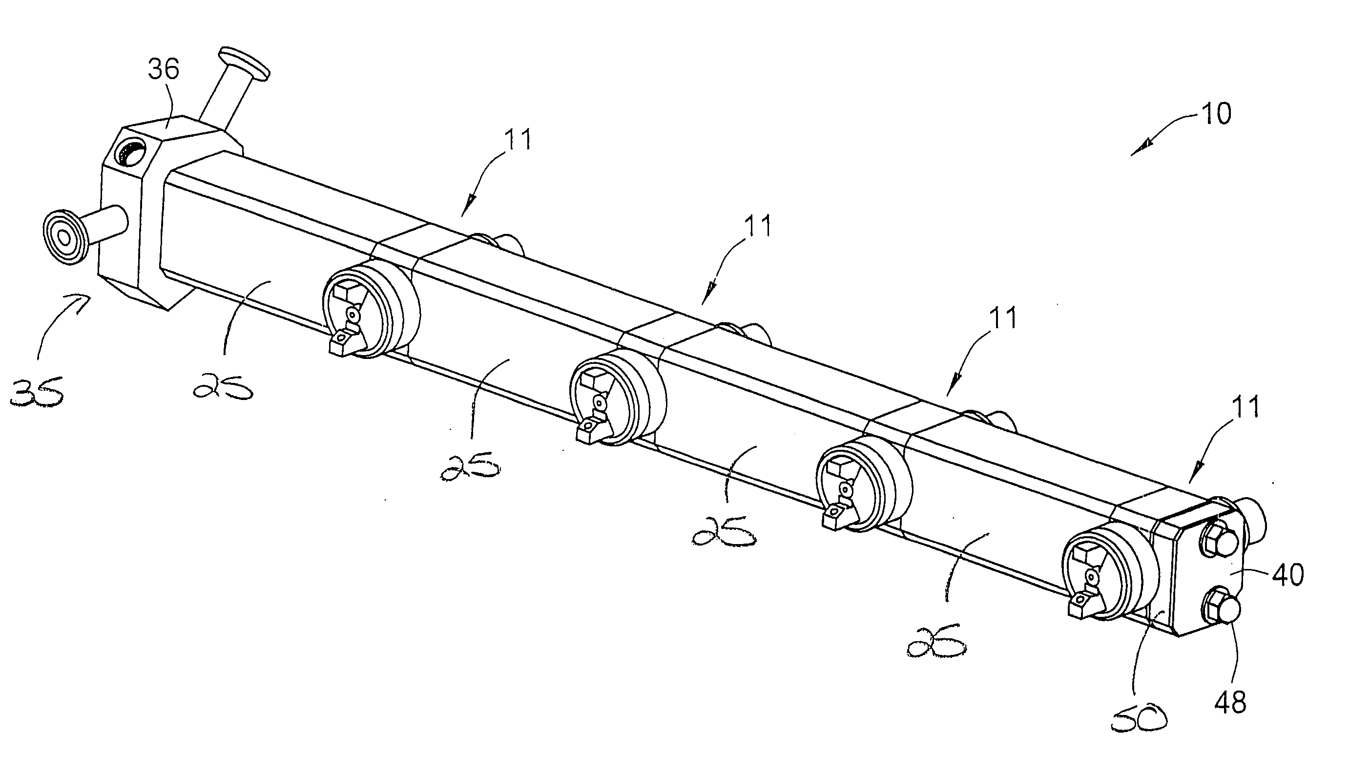
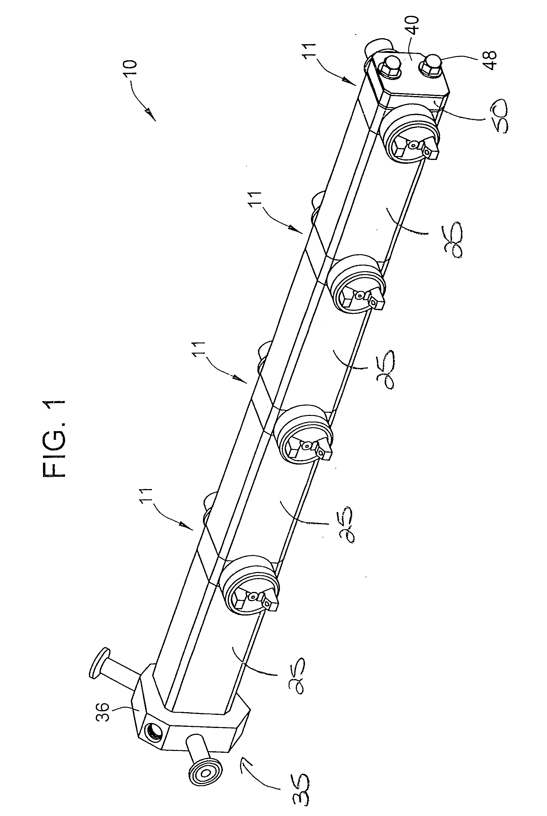
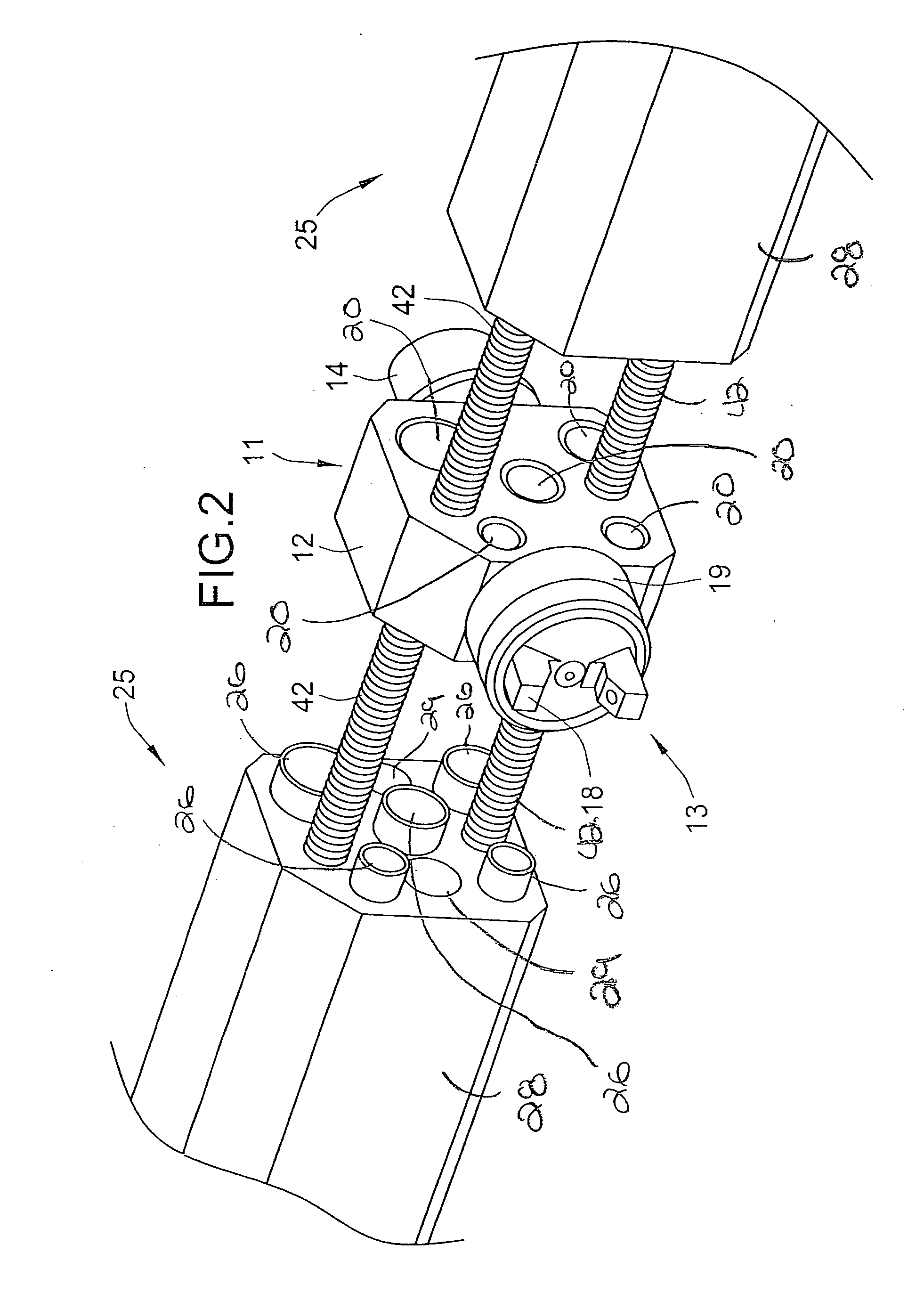
[0028] Referring now more particularly to FIG. 1 of the drawings, there is shown an illustrated modular spray gun manifold 10 in accordance with the invention. The manifold 10 includes a plurality of spray gun modules 11 each of which includes a rectangular block-shaped body 12, a spray nozzle assembly 13 supported at one end of the module body 12, and an actuator 14 supported at the opposite end of the module body 12. The basic structure and mode of operation of the spray gun modules are known in the art, for example, as shown in U.S. Pat. No. 5,707,010 assigned to the same assignee of the present application, the disclosure of which is incorporated herein by reference. The overall structure and mode of operation of the spray gun modules 11 should be understood to be illustrative of only one example of spray device with which the present invention may be used.

[0029] The spray nozzle assembly 13 of the illustrated spray gun module 11 is an external mix type of spray nozzle, namely ...


PUM


Abstract

A modular automatic spray gun manifold is provided. The manifold includes a plurality of spray gun modules arranged in an array in laterally spaced relation from each other. A junction element is arranged at an upstream end of the manifold for introducing fluid into the manifold. A first support assembly is arranged between the junction element and a first spray gun module in the spray gun module array for supporting the first spray gun module relative to the junction element. The first support assembly includes a plurality of fluid conduits for supplying fluid to the first spray gun module. One or more second support assemblies with one second support assembly are arranged between each adjacent pair of spray gun modules in the array of spray gun modules for supporting the adjacent pair of spray gun modules relative to each other. Each second support assembly includes a plurality of fluid conduits for communicating fluid between the adjacent spray gun modules such that fluid introduced into the manifold through the junction element is communicated to each spray gun module. The first support assembly and each second support assembly include an interior space through which their respective plurality of fluid conduits extend and a heat transfer fluid inlet for communicating a hot heat transfer fluid into the interior space of the respective support assembly.

Description

CROSS-REFERENCE TO RELATED APPLICATIONS [0001] This patent application is a continuation-in-part of copending U.S. patent application Ser. No. 10 / 810,997, filed Mar. 26, 2004, which claims the benefit of U.S. Provisional Patent Application No. 60 / 457,946, filed Mar. 27, 2003.FIELD OF THE INVENTION [0002] The present invention relates generally to spray gun type liquid spray devices, and more particularly, to an automatic spray gun manifold having a modular construction. BACKGROUND OF THE INVENTION [0003] Modular spray gun manifold assemblies that include a plurality of laterally spaced spray guns supported in a row for discharging an elongated spray pattern are known. Such manifolds are used, for example, in pill coating machines in the pharmaceutical industry. In these applications, the manifold must be movable between a predetermined operative position relative to a rotatable pill tumbler for applying the coating and a position in which the manifold is arranged away from the tumbl...

Claims


Application Information

Patent Timeline
Patent Type & Authority Applications(United States)
IPC IPC(8): B05B1/14B05B7/08
CPCB05B7/0815B05B7/0884B05B15/069B05B13/0257B05B7/1653B05B15/658B05B15/58
Inventor HUFFMAN, DAVID C.FRECHETTE, RUSSELL R.
Owner SPRAYING SYST
Why Eureka
Try Eureka