Encapsulated preformed shapes

a technology of pre-formed shapes and encapsulated materials, applied in the field of encapsulated pre-formed shapes, can solve the problems of not being compatible with another manufacturing process, material that works well for one manufacturing process may not be compatible with another, and relatively fine-grained material may not be compatible with a manufacturing process, so as to extend the usable life of the composite wear part

Active Publication Date: 2014-08-05
SPOKANE INDS
View PDF5 Cites 9 Cited by
  • Summary
  • Abstract
  • Description
  • Claims
  • Application Information

AI Technical Summary

Benefits of technology

[0006]This disclosure relates to composite parts that are subject to wear (so called “wear parts”), and techniques for manufacturing such composite wear parts. The composite wear parts include encapsulated preformed ceramic shapes, cast in situ or otherwise encapsulated in a base metal. The encapsulated preformed ceramic shapes are more easily handled or manipulated during manufacturing processes than handling smaller fine-grained materials. Because the encapsulated preformed ceramic shapes are more easily handled, the mechanisms and / or steps required in the manufacturing process to produce the composite wear parts are reduced compared to handling the smaller fine-grained material, thereby reducing the cost of the composite wear parts.
[0007]The composite wear parts may be configured to withstand, resist, or protect against abrasion and / or impacts. The composite components exhibit improved resistance to wear and, therefore, have longer usable life than wear parts formed of a base metal alone. Composite wear parts may be used to improve a usable life of virtually any wear part. For example, the composite wear parts may be used as impact crusher wear parts, mining wear parts, oil field wear parts, construction wear parts, or any other industry utilizing parts and / or machinery in abrasive conditions.
[0013]In some examples, the multiple layers of uniform arrays of preformed ceramic shapes may increase a total depth or thickness of ceramic material exposed to an abrasion, thereby extending a usable life of the composite wear part. For example, two or more layers of arrays of preformed ceramic shapes may be arranged in an adjacent, subjacent, and / or overlapping manner. The layers of arrays of preformed ceramic shapes may be arranged such that a preformed ceramic shape in a top layer covers, minimizes, or eliminates an interstitial space between preformed ceramic shapes in a lower layer. The top layer may be exposed to an abrasion first, eventually wearing down to the lower layer, after which the lower layer is then exposed to the abrasion.

Problems solved by technology

However, manufacturing composite components is often challenging due to the different properties of materials used to form the composite components.
A material that works well for one manufacturing process may not be compatible with another manufacturing process.
For example, a relatively hard fine-grained material may not be compatible with a manufacturing process where the relatively fine-grained material is to be precisely placed in a base material.
As such, to precisely place the fine-grained material in the base material, additional mechanisms and / or steps may be required in the manufacturing process to produce the component, thereby increasing the component's costs.

Method used


Image

  • Encapsulated preformed shapes
  • Encapsulated preformed shapes
  • Encapsulated preformed shapes

Examples


example composite

Wear Parts

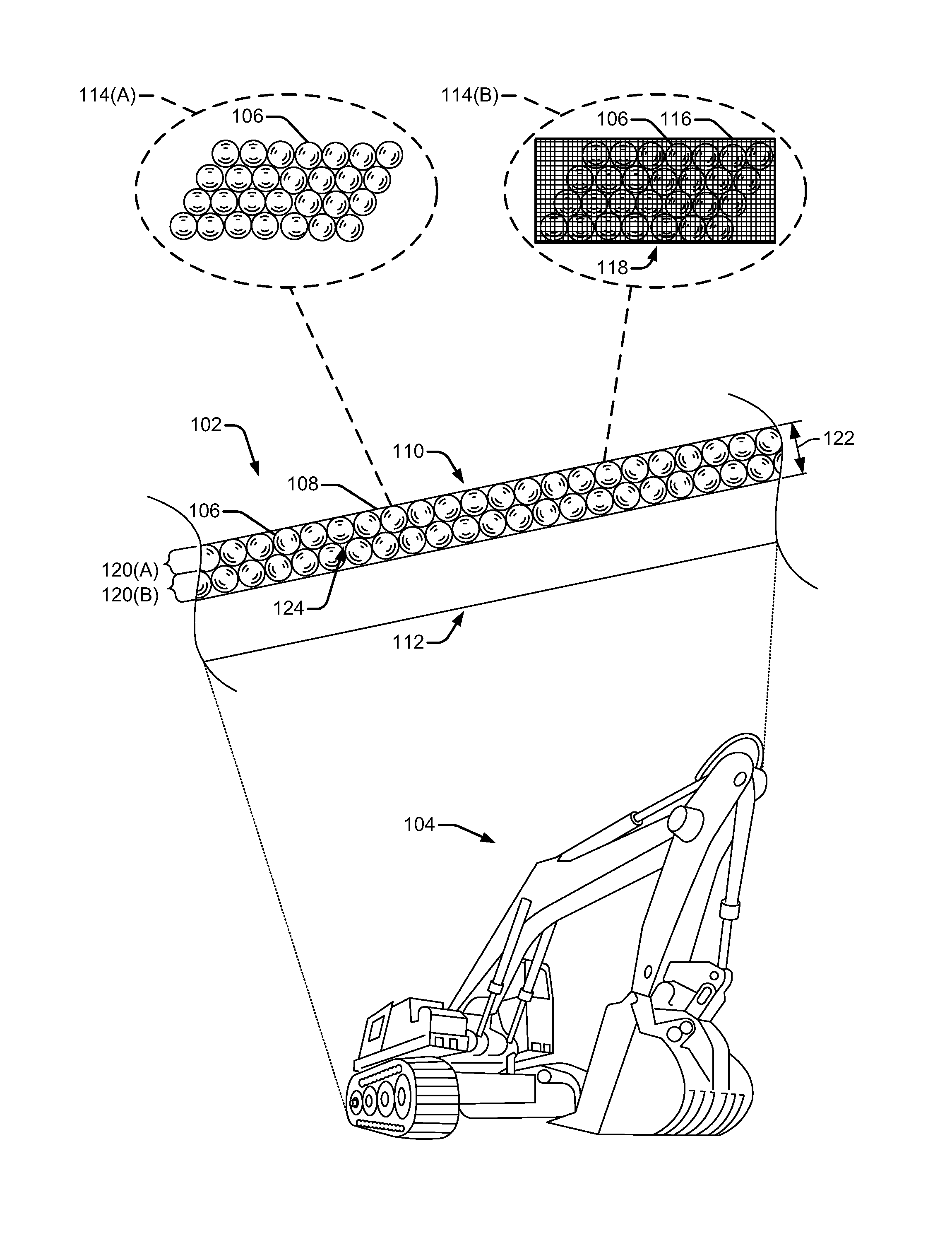
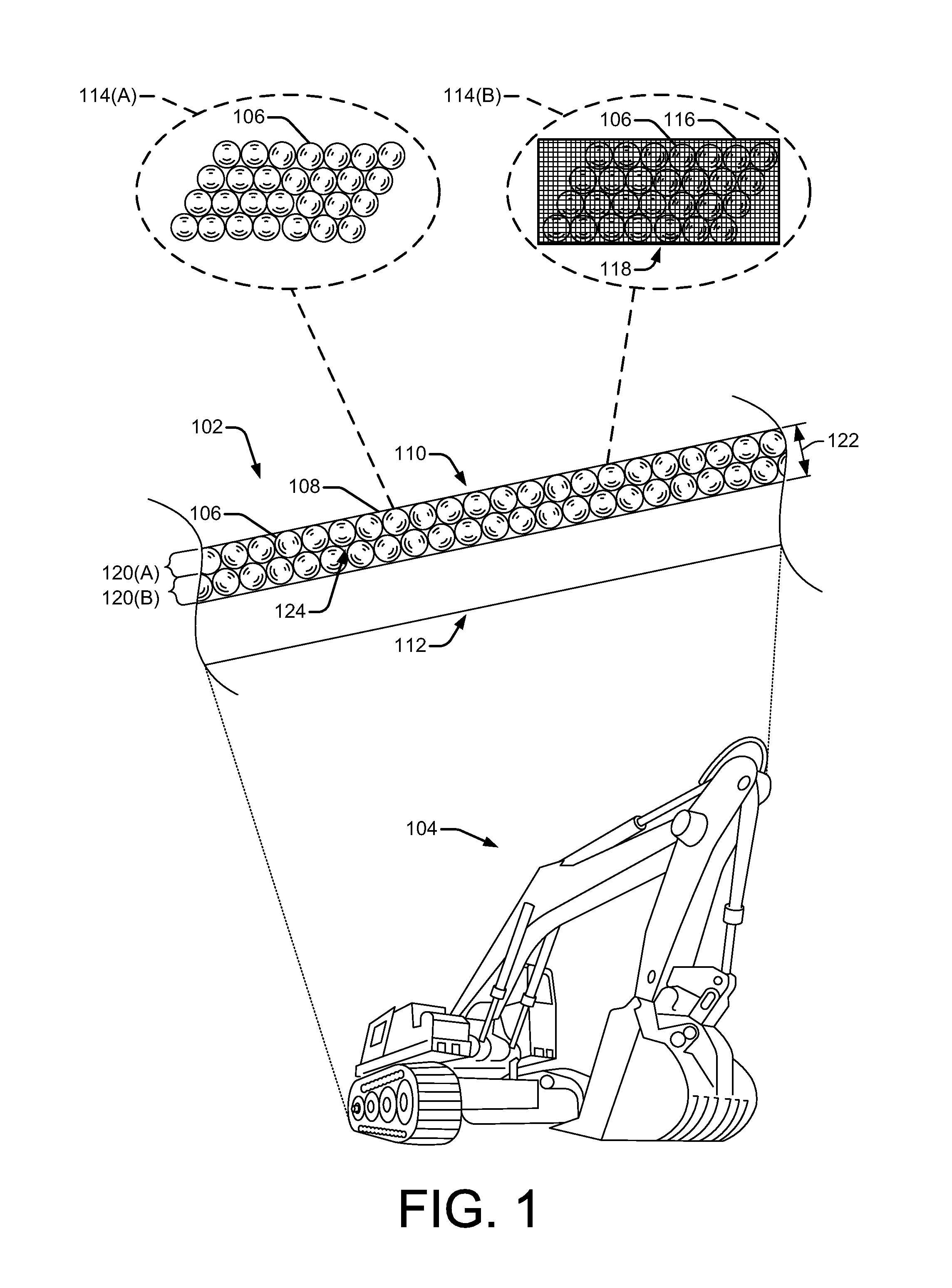
[0041]This section describes exemplary composite wear parts including a plurality of preformed ceramic shapes embedded in a base metal.

[0042]In some implementations, the plurality of preformed ceramic shapes may include a plurality of elements having a uniform, preformed geometry. The preformed geometry being such that the plurality of preformed ceramic shapes are configured to pack together in a uniform way to provide for being positioned at a location in the composite wear part exposed to an abrasion. These and numerous other composite wear parts can be formed according to the techniques described in this section.

[0043]Metal / ceramic composite materials are well suited to abrasion-resistant applications due to the characteristics of the materials. For example, metals typically provide a relatively high strength-to-weight ratio and a high toughness, while ceramics have a relatively high hardness.

[0044]FIG. 1 is a side view diagram of a composite wear part 102 used, for exa...


PUM

PropertyMeasurementUnit
outer diameteraaaaaaaaaa
diameteraaaaaaaaaa
diameteraaaaaaaaaa

Abstract

Composite wear parts including encapsulated preformed ceramic shapes are disclosed. Preformed ceramic shapes are embedded in a metal alloy to protect the base metal from abrasion. The preformed ceramic shapes may have a uniform, preformed geometry that provides for packing the preformed ceramic shapes together in a uniform way. The preformed ceramic shapes may be positioned at a location in the composite wear part exposed to an abrasion without using a binding agent. The preformed ceramic shapes may also be contained in a porous container. A truss structure may be integrated in the preformed ceramic shapes to compartmentalize the preformed ceramic shapes into multiple isolated sub regions to stiffen the composite wear parts.

Description

BACKGROUND[0001]Wear resistant components are desirable in a variety of industrial, commercial, and military applications. For example, mining, construction, heavy equipment, automotive, military, and other applications rely on components that are resistant to wear.[0002]Recently, composite components formed of multiple materials having different material properties (i.e., high hardness and toughness) have been used.[0003]However, manufacturing composite components is often challenging due to the different properties of materials used to form the composite components. For example different materials often have different handling properties. A material that works well for one manufacturing process may not be compatible with another manufacturing process. For example, a relatively hard fine-grained material may not be compatible with a manufacturing process where the relatively fine-grained material is to be precisely placed in a base material. As such, to precisely place the fine-gra...

Claims


Application Information

Patent Timeline
Patent Type & Authority Patents(United States)
IPC IPC(8): B23Q23/00B23Q27/00B32B5/16
CPCB23Q23/00B23Q27/00B32B5/16B22D19/02B22D19/14Y10T428/12007Y10T428/13Y10T428/24008Y10T428/25Y10T428/252
Inventor GROZDANICH, ROD ALANKACZMAREK, EDWARD ROBERT
Owner SPOKANE INDS
Why Eureka
Try Eureka