Thermal physical vapor deposition source using pellets of organic material for making OLED displays

a technology of physical vapor deposition and organic material, which is applied in the direction of vacuum evaporation coating, chemical vapor deposition coating, coating, etc., can solve the problems of non-uniform vapor flux of organic material to emanate along a length the width dimension of the slit is reduced, and the formation of an organic layer thereon that will have a non-uniform layer thickness

Inactive Publication Date: 2005-01-27
GLOBAL OLED TECH
View PDF8 Cites 164 Cited by
  • Summary
  • Abstract
  • Description
  • Claims
  • Application Information

AI Technical Summary

Benefits of technology

The present invention has two main benefits: it allows for larger structures to have evenly distributed layers made up of both an active ingredient and a diluent material through thermally driven processes (thermal physical vapor deposition). Additionally, this technology enables extended periods of evaporation compared to traditional methods where components are simultaneously heated together. This results in more efficient use of the substrate being processed during production.

Problems solved by technology

The patent text discusses the problem of non-uniformity in the deposition of organic materials in devices such as organic light-emitting devices. This can be caused by the use of a point source or a linear source of vaporization. The text describes various methods for improving the uniformity of the deposition, such as using a gas curtain or a reactor vessel. The technical problem addressed in the patent text is to provide a more uniform layer thickness of the organic layer in such devices.

Method used


Image

  • Thermal physical vapor deposition source using pellets of organic material for making OLED displays
  • Thermal physical vapor deposition source using pellets of organic material for making OLED displays
  • Thermal physical vapor deposition source using pellets of organic material for making OLED displays

Examples


Embodiment Construction

The term “substrate” denotes at least a portion of an OLED display, which includes one or more layers onto which another organic layer is to be formed.

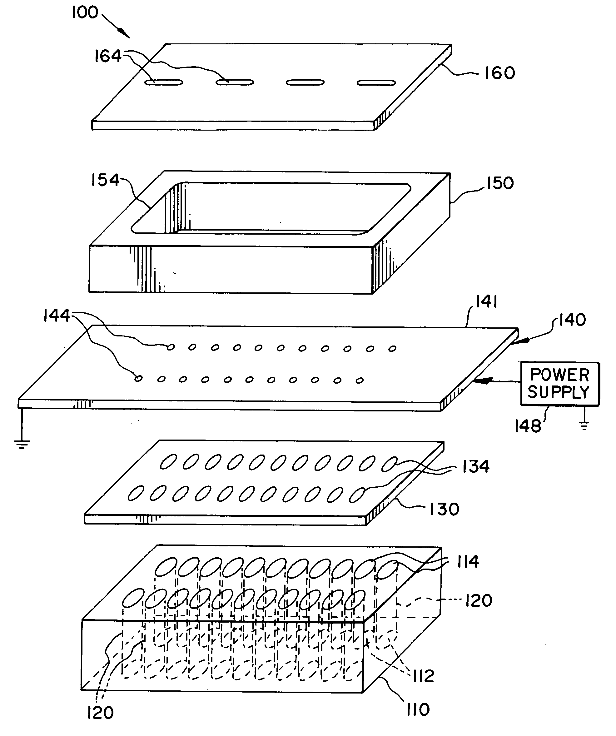
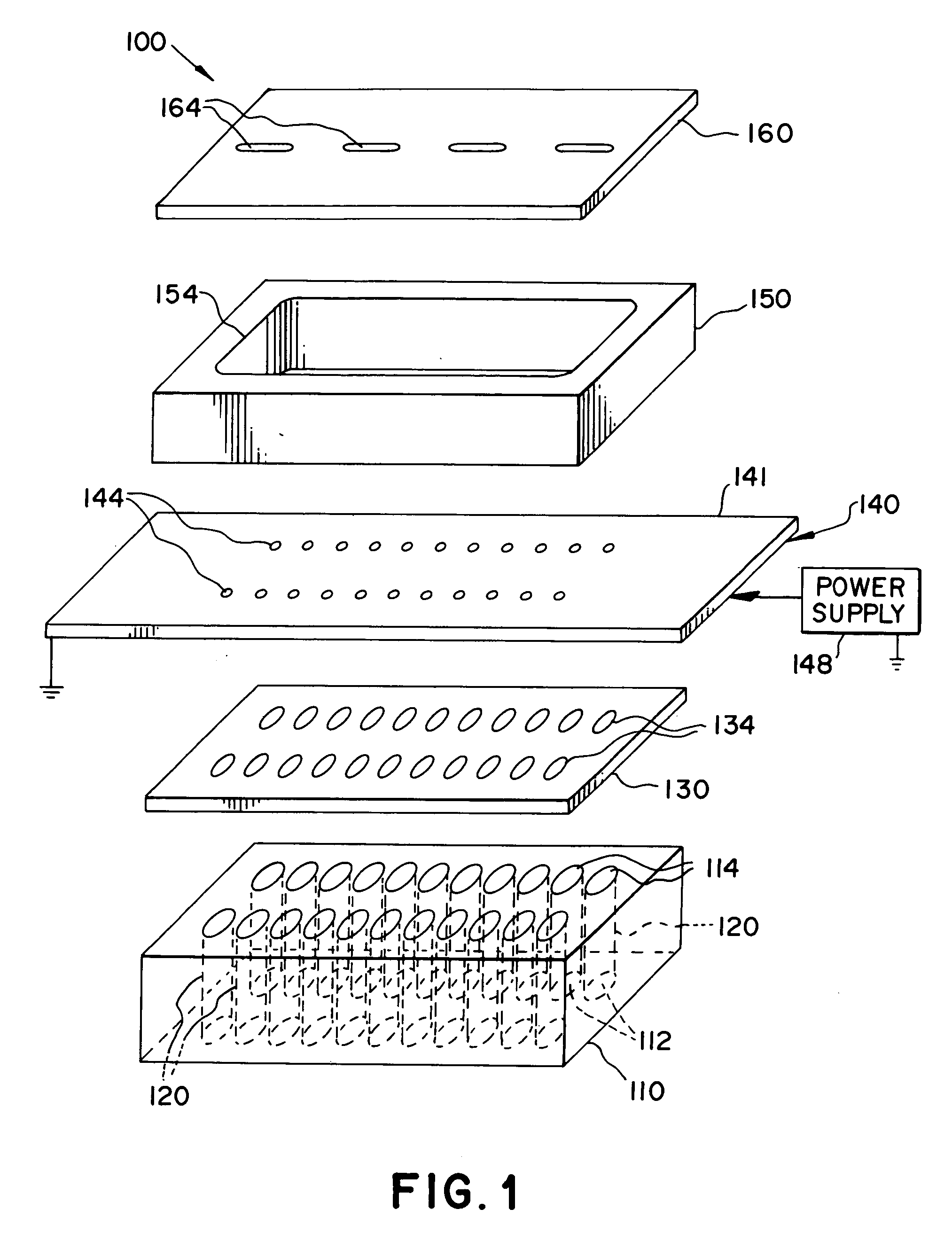
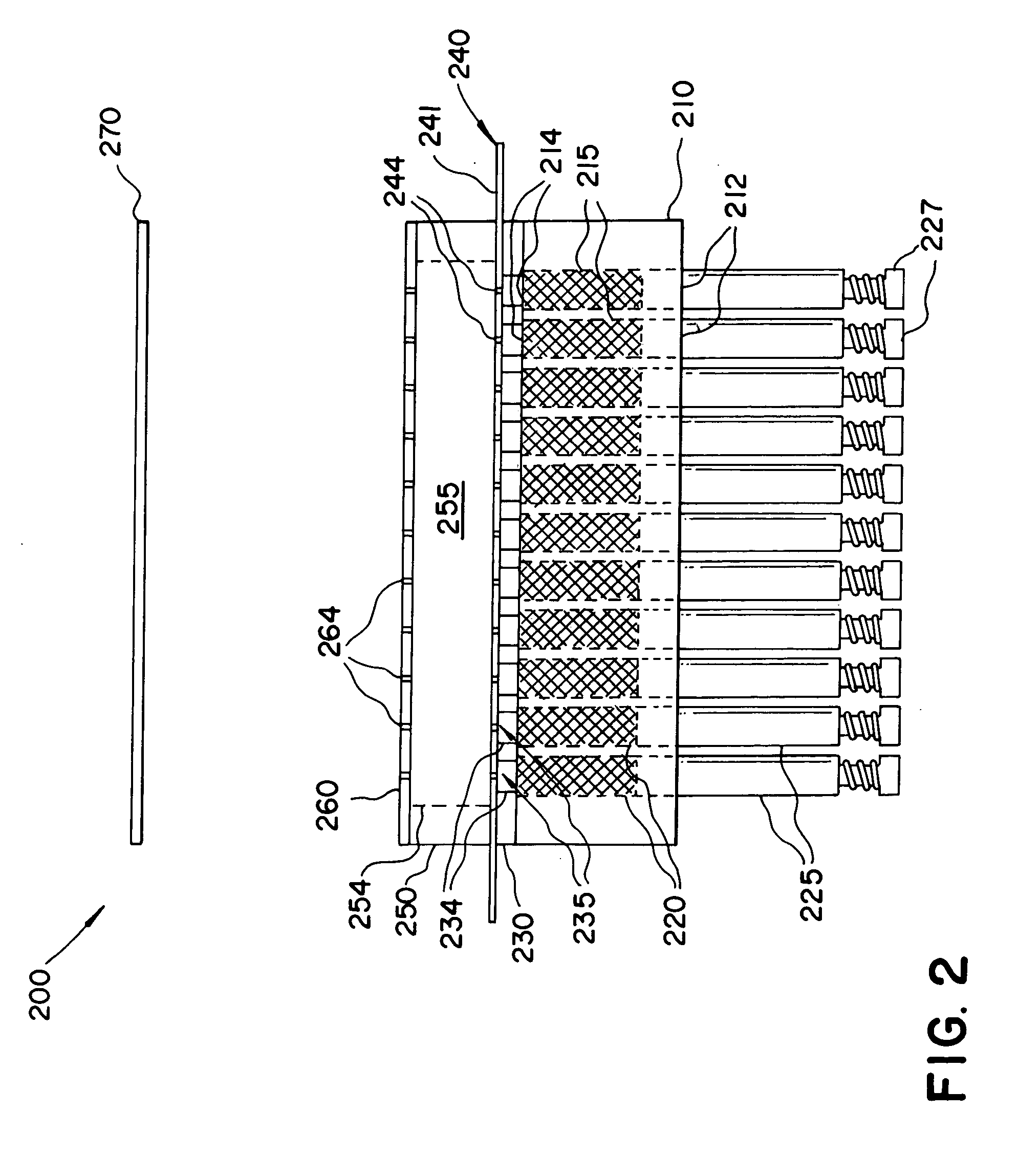
Turning to FIG. 1, a thermal physical deposition source 100 is illustrated, wherein a housing 110, defining a plurality of spaced passages 120, each spaced passage 120 having a closed first end 112 and an open second end 114 is shown. The spaced passages 120 can be of any shape and size and are fabricated such that compacted pellets 215 (see FIG. 2) of organic materials can be inserted through the open second end 114.

The housing 110 can be formed from thermally insulating materials such as high temperature glasses like quartz, alumino-boro-silicate glass and ceramics like alumina, zirconia, boron nitride, or magnesia. The purpose of using thermally insulating materials is to manage the thermal characteristics of the housing 110 when compacted pellets 215 used have more than one organic component, the details of which will be desc...


PUM

PropertyMeasurementUnit
Temperatureaaaaaaaaaa
Electrical conductivityaaaaaaaaaa
Flow rateaaaaaaaaaa

Abstract

A thermal physical vapor deposition source for vaporizing compacted pellets of organic materials onto a surface of a substrate in forming a display, including a housing defining a plurality of spaced passages each for receiving compacted pellets, a cover plate over the housing, with a first plurality of openings corresponding to the spaced passages of the housing and an electrical heater structure disposed over the cover plate. The thermal physical vapor deposition source further including an aperture plate, disposed over the electrical heater structure, an electrically insulating spacer member located between the electrical heater structure and an aperture plate, and circuitry for applying current to the electrical heater structure to produce heat sufficient to vaporize the pellets and permit vapor efflux of materials to pass through the cover plate, the heater structure, the electrically insulating spacer member and the aperture plate, onto the substrate.

Description


Claims


Application Information

Patent Timeline
Owner GLOBAL OLED TECH
Why Eureka
Try Eureka