Finger operated spray pump

a finger-operated, spray pump technology, applied in the direction of spraying apparatus, liquid spraying apparatus, fire rescue, etc., can solve the problems of reducing the stroke length of the piston stroke compared with the stroke length of the finger itself, unable to achieve higher pressure anyway, and unable to achieve high pressur

Inactive Publication Date: 2005-01-27
BOEHRINGER INGELHEIM MICROPARTS
View PDF8 Cites 8 Cited by
  • Summary
  • Abstract
  • Description
  • Claims
  • Application Information

AI Technical Summary

Benefits of technology

[0006] A primary object of the present invention is to provide a finger operated spray pump system that is capable of atomising small doses of liquid in order to produce a “dry” spray of liquid, i.e., a spray of liquid using much less solvent than prior art aerosol finger operated spray pumps.

Problems solved by technology

Those pumps operate at pressures of much less than 10 bar anyway and do not lend themselves to higher pressures, as the cylinder / piston-valve arrangement is molded of thin plastics.
However, in the prior art, it is understood that higher pressures cannot be achieved anyway, because the average operating force provided by a finger on the hand of an operator will normally be around 10 N and will, even in the extreme, not exceed 30 N.
This means that large quantities of solvent, such as alcohol and water, are required in the formulation of the liquid to lower the viscosity of the liquid.
The high-level solvent formulations of liquid used in conventional aerosol finger operated spray pumps leads to sprays that are recognized by the user as “wet.” Reducing the amount of solvent means that the liquid becomes more viscous and more difficult spray.
However, this reduces the piston stroke in comparison with the stroke length of the finger itself.

Method used


Image

  • Finger operated spray pump
  • Finger operated spray pump
  • Finger operated spray pump

Examples


Embodiment Construction

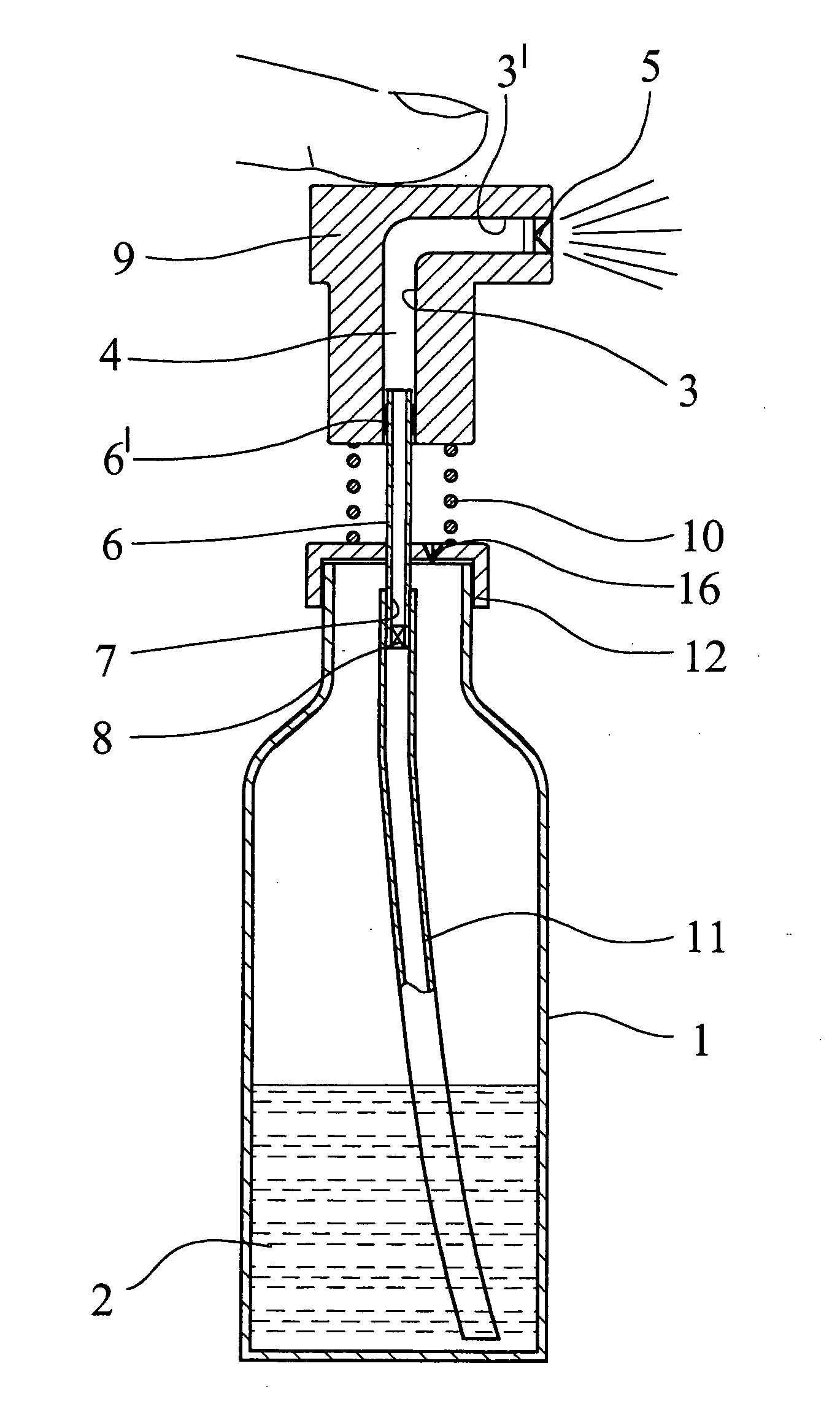
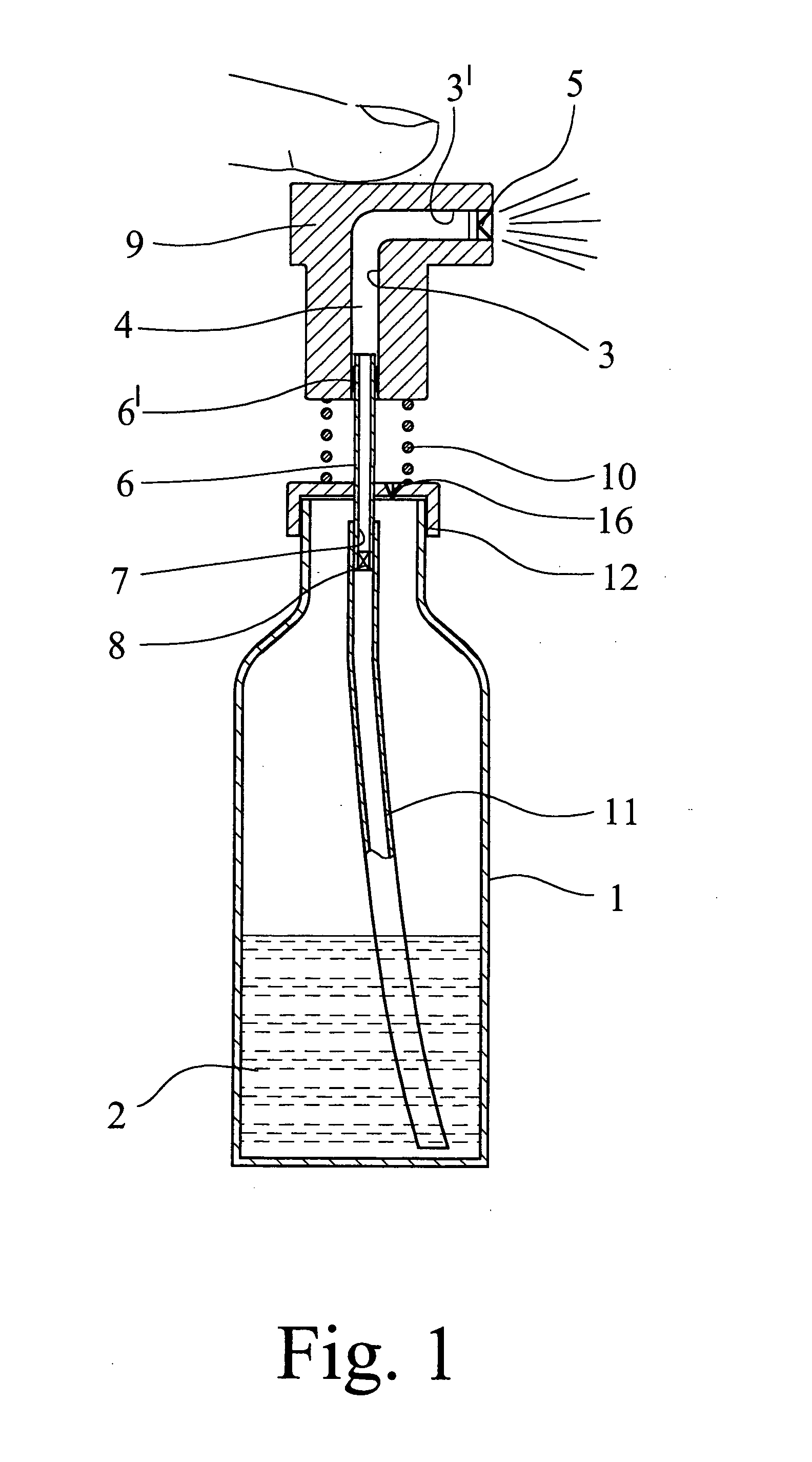
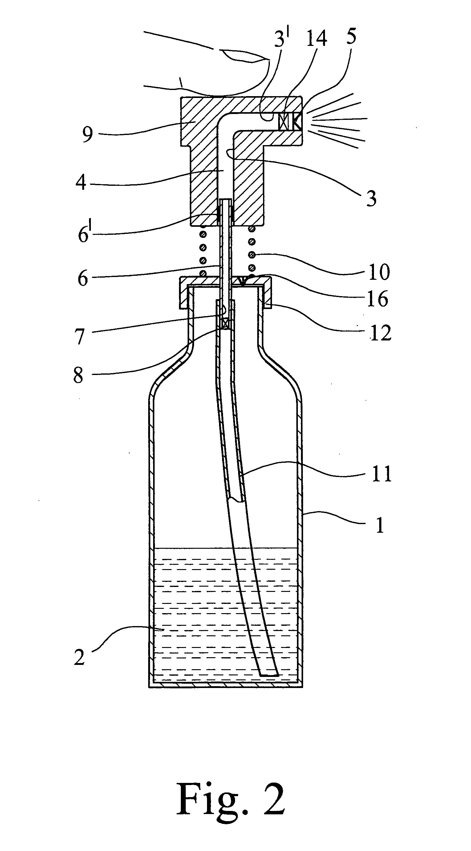
[0022]FIG. 1 shows a first embodiment of the invention which is a finger operated spray pump. This finger operated spray pump comprises a liquid reservoir 1, which, here, is in the form of a rigid container, intended to contain a supply of liquid 2. A cylinder 3 contains a pump volume of liquid 4. The cylinder 3 is connected at one end to an atomizer 5 and is intended to contain a portion of liquid from the reservoir 1, a part of which is to be ejected through the atomizer 5 in a spray stroke.

[0023] The atomizer 5 may be of the swirl chamber type with a swirl chamber in front of the nozzle exit. However, it may be of a double jet impeller type or of any other type realizing a mechanical brake up nozzle character. Ideas for such atomizer 5 can be found, for example, in published German Patent Application DE 101 54 237 A1. However, the atomizer 5 may as well produce a jet of liquid if a specific requirement has to be met.

[0024]FIG. 1 shows that a piston 6 is sealingly mounted within...


PUM


Abstract

A finger operated spray pump has a liquid reservoir (1), a cylinder (3) for containing a portion of the liquid from the reservoir (1) which is connected at one end to an atomizer (5), a piston (6) sealingly mounted within the cylinder (3) and movable within the cylinder (3) in a spray stroke, a passageway (7) connecting the cylinder (3) with the liquid reservoir (1), a one way valve (8) at the passageway (7) for allowing a flow of liquid only from the supply of liquid (2) into the cylinder (3), and a finger operated actuator (9) which is displaceable relative to the liquid reservoir (1). The outer diameter of the piston (6) and the corresponding inner diameter of the cylinder (3) is between about 0.5 mm and about 4.0 mm, the nozzle diameter of the atomizer (5) is between 15 μm and 150 μm, the operating pressure within the cylinder (3) during the spray stroke with average finger force is between 10 bar and 400 bar and the atomizer (5), the cylinder (3), the piston (6) and the one way valve means (8) are designed to withstand the operating pressure.

Description

BACKGROUND OF THE INVENTION [0001] 1. Field of the Invention [0002] The invention is related to finger operated spray pumps for spraying aerosol products by means of an atomizer arrangement. In particular, the invention directed to a finger operated spray pump having a liquid reservoir, a cylinder connected at one end to an atomizer to contain a portion of liquid from the reservoir, a part of which is to be ejected through the atomizer, a piston sealingly mounted within the cylinder and movable within and relative to the cylinder in a spray stroke such that the volume within the cylinder is reduced and a corresponding amount of the liquid in the cylinder is ejected through the atomizer, and in a return stroke such that the volume within the cylinder is increased and a corresponding amount of the liquid is drawn from the supply of liquid into the cylinder, a passageway means connecting the cylinder with the supply of liquid in the liquid reservoir, a one way valve means at the passag...

Claims


Application Information

Patent Timeline
Patent Type & Authority Applications(United States)
IPC IPC(8): A62C11/00B05B11/00
CPCB05B11/0043B05B11/306B05B11/3004B05B11/3001B05B11/1004B05B11/026B05B11/1001B05B11/106
Inventor ROHRSCHNEIDER, MARC
Owner BOEHRINGER INGELHEIM MICROPARTS
Why Eureka
Try Eureka