

Attaching device for attaching stopping or lashing means
- Summary
- Abstract
- Description
- Claims
- Application Information
AI Technical Summary
Benefits of technology
Problems solved by technology
Method used
Image

Examples
Embodiment Construction
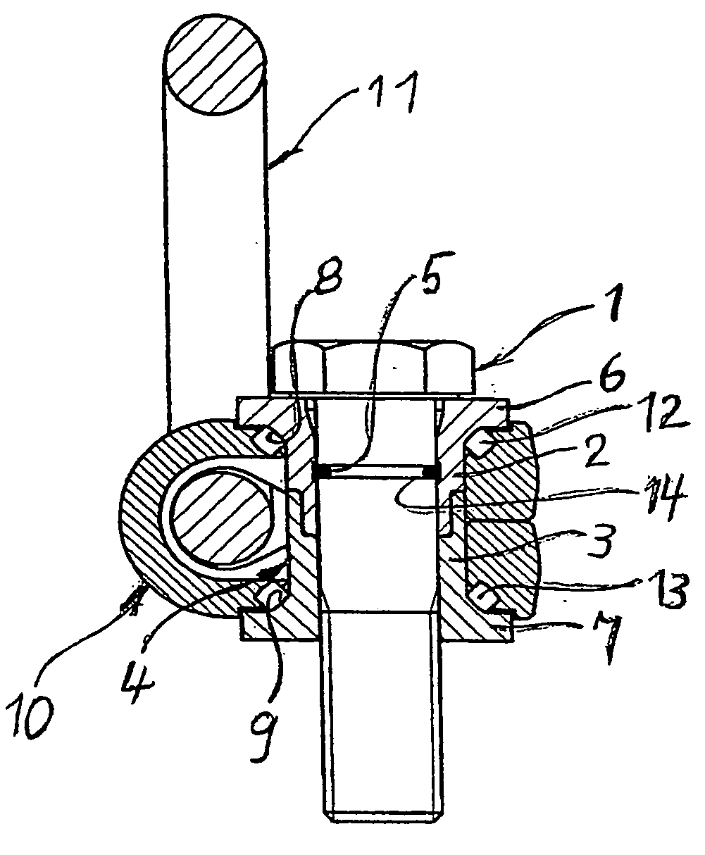
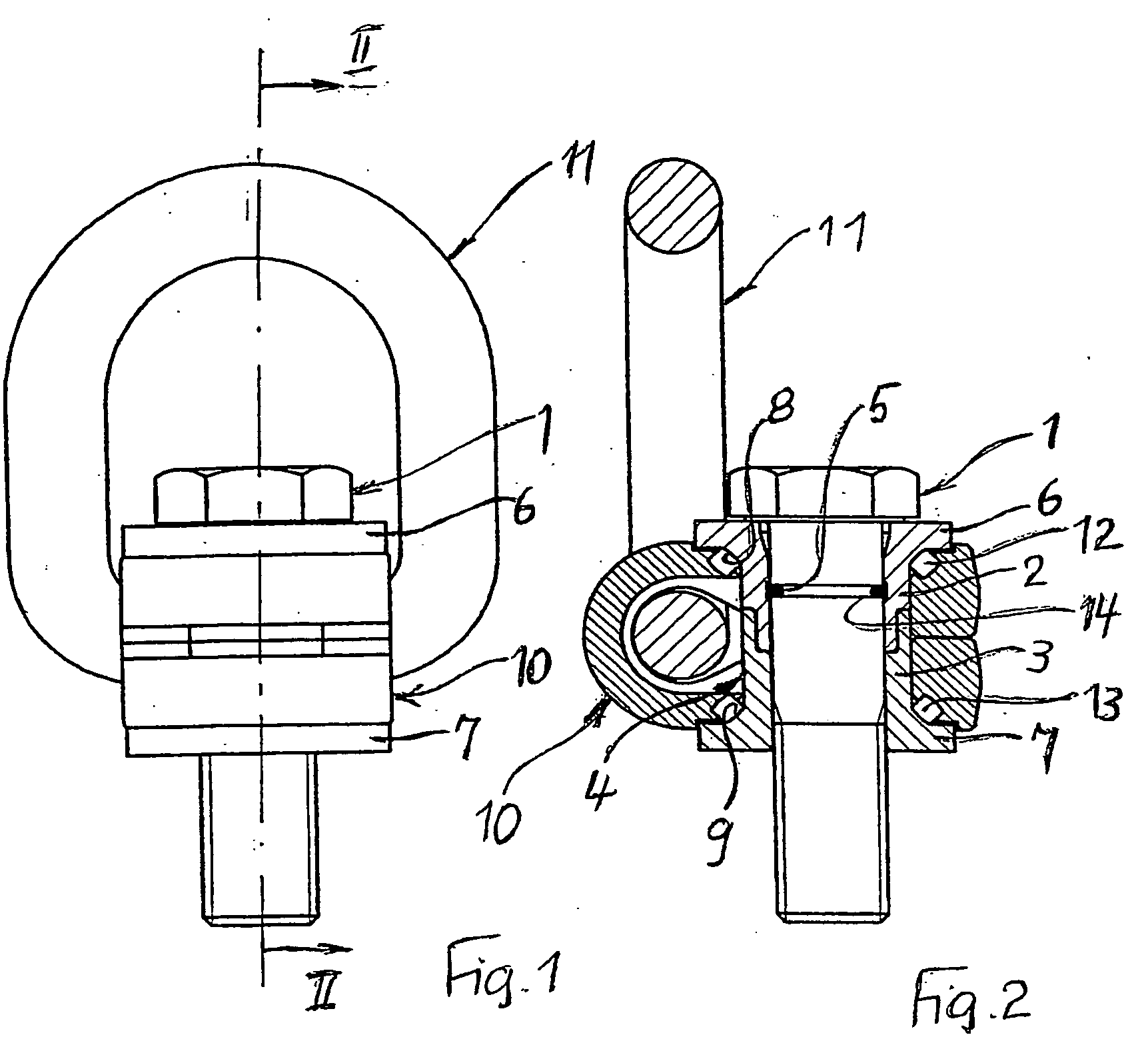
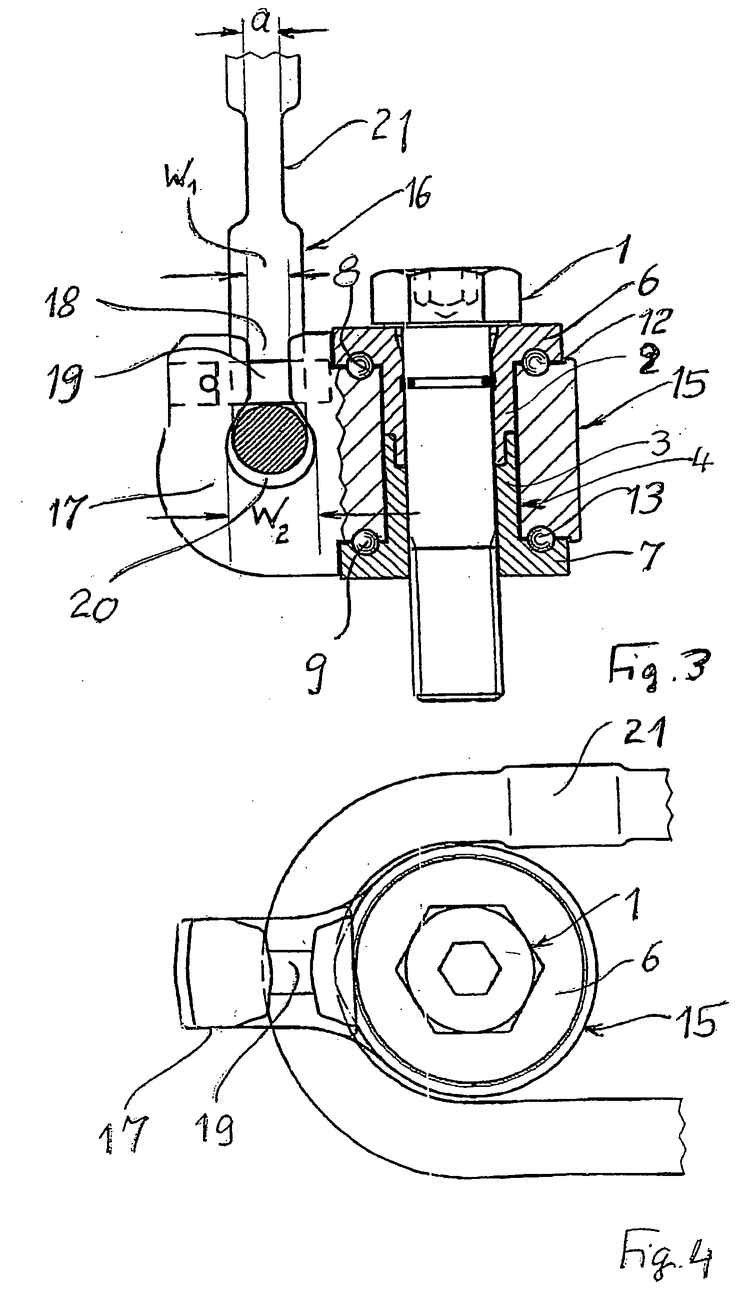
[0003] The object of the invention, in the case of an attachment device of the type in question, is to increase the relative movement capability between the fastening element and the connecting element by replacing the sliding mounting with an easy-to-install rolling-contact mounting, a high level of tilting resistance of the connecting element being desired at the same time. This object is achieved, in the case of an attachment device of generic type, in that the connecting element is supported on the bushing, in the region of the annular flanges of the bushing, via a series of rolling-contact bodies in each case.
[0004] The attachment device according to the invention is quick and easy to assemble. The level of tilting resistance of its connecting element is high, on account of the use of two series of rolling-contact bodies which are spaced apart from one another by the greatest possible distance, and the rotatability of the connecting element leaves nothing to be desired, even f...
PUM
 Abstract
Description
Claims
Application Information