Object tracking method and object tracking apparatus

a technology of object tracking and object tracking, applied in direction finders, instruments, television systems, etc., can solve the problem of system being more likely to overlook an intruder's obj

Inactive Publication Date: 2005-01-27
KOKUSA ELECTRIC CO LTD
View PDF8 Cites 111 Cited by
  • Summary
  • Abstract
  • Description
  • Claims
  • Application Information

AI Technical Summary

Benefits of technology

It is another object of the present invention to provide an object tracking method and an object tracking apparatus which are capable of tracking an object, even when a field under monitorin...

Problems solved by technology

The aforementioned monitoring system is disadvantageous in that the TV camera can capture private houses which are not to be monitored, and that essentia...

Method used


Image

  • Object tracking method and object tracking apparatus
  • Object tracking method and object tracking apparatus
  • Object tracking method and object tracking apparatus

Examples


Embodiment Construction

Several embodiments of the present invention will be described with reference to the accompanying drawings, wherein like components are designated the same reference numerals.

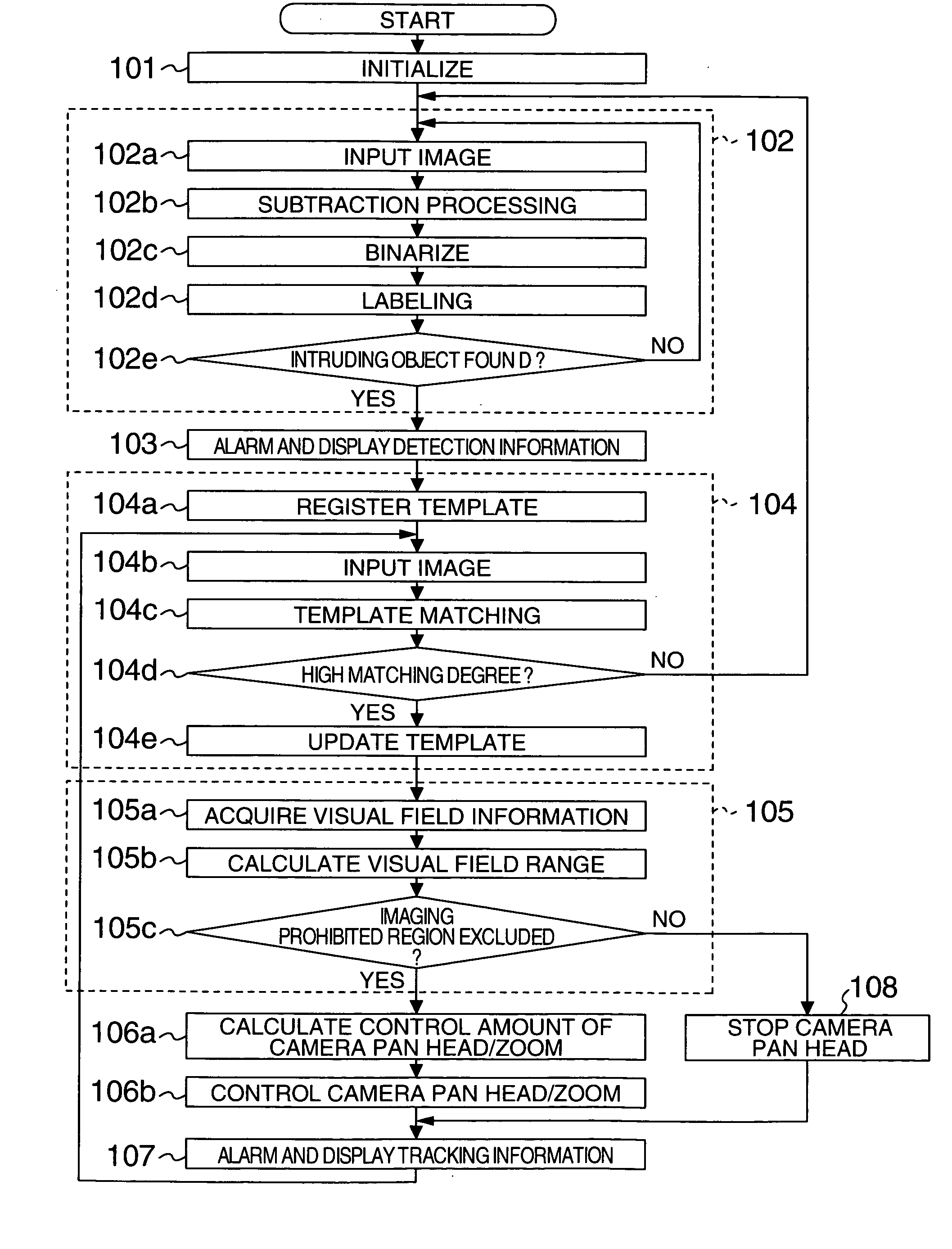
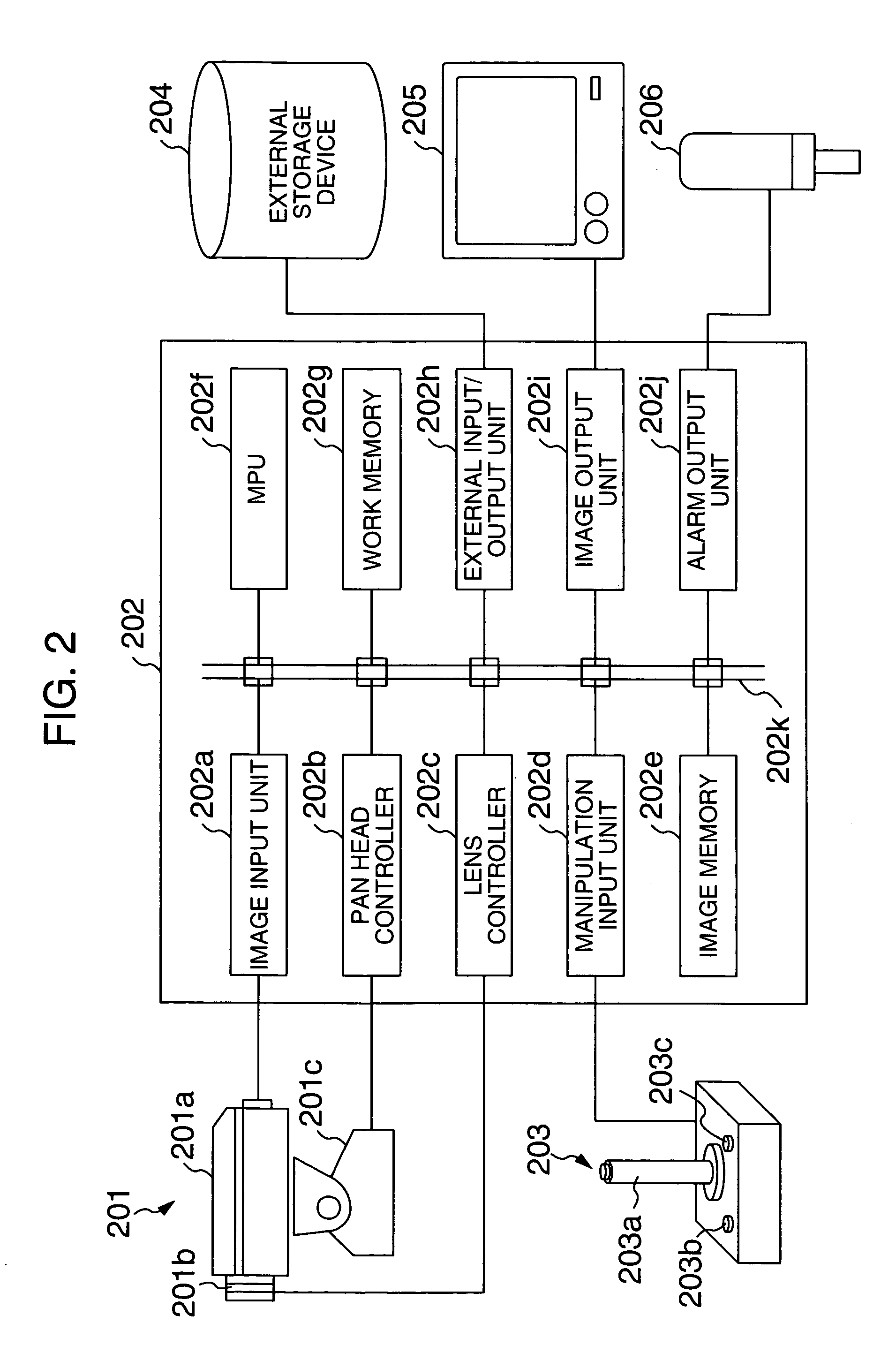
One embodiment of the present invention will be first described with reference to FIGS. 1 and 2. FIG. 2 is a block diagram illustrating the configuration of a system for embodying the present invention. The system illustrated in FIG. 2 has an imaging device 201 which is composed of a TV camera 201a, a zoom lens (imaging lens) 201b, and a camera pan and tilt head (camera driving mechanism, hereinafter referred to as camera pan head) 201c. A signal processor 202 comprises an image input unit 202a, a pan and tilt head controller (hereinafter referred to as pan head controller) 202b, a lens controller 202c, a manipulation input unit 202d, an image memory 202e, an MPU (Micro Processing Unit) 202f, a work memory 202g, an external input / output unit 202h, an image output unit 202i, an alarm output unit 202j, and a d...


PUM


Abstract

An object tracking apparatus consisting of an imaging device, a signal processor for processing a video signal generated by the imaging device, and a display for displaying the result of processing performed by the signal processor. An intruding object is detected within a field under monitoring based on a video signal captured by the imaging device, and the imaging device is controlled in response to motions of the intruding object to track the object. The position of a visual field range of the imaging device is calculated, and panning and tilting of the imaging device and an imaging lens are controlled such that the calculated position of the visual field range of the imaging device does not include an imaging prohibited region positioned within the field under monitoring.

Description

BACKGROUND OF THE INVENTION The present invention relates to an object tracking method and an object tracking apparatus, and more particularly, to an object tracking method and an object tracking apparatus for controlling an imaging field (visual field range) of an imaging device in accordance with motions of an object. While remote monitoring systems relying on an imaging device such as a TV (television) camera have been conventionally used in wide applications, many of them are so-called manned monitoring systems which employ a watchman who is monitoring while viewing images displayed on a monitor. In this type of manned monitoring system, a watchman is required to watch images displayed on a monitor at all times to identify in real time an intruding object such as a human, a car or the like which can come into a field under monitoring, so that a large burden is imposed on the watchman. Since a human has limitations in concentration, the manned monitoring system experiences over...

Claims


Application Information

Patent Timeline
IPC IPC(8): G01S3/781G08B13/194H04N7/18
CPCG01S3/781G08B13/19602G08B13/19604G08B13/19608H04N7/183G08B13/19686G08B13/19689G08B13/19691G08B13/19652H04N7/18
Inventor ITO, WATARUFUJII, MIYUKI
Owner KOKUSA ELECTRIC CO LTD
Why Eureka
Try Eureka