Instruments and method for inserting an intervertebral implant

a technology of instruments and methods, applied in the field of intervertebral implants, can solve the problems of extreme delicate area in which to insert an intervertebral implant, and achieve the effect of stabilizing the implan

Inactive Publication Date: 2005-01-27
CENTINEL SPINE LLC
View PDF98 Cites 375 Cited by
  • Summary
  • Abstract
  • Description
  • Claims
  • Application Information

AI Technical Summary

Benefits of technology

[0013] In accordance with another embodiment of an insertion instrument and its accompanying method, there is provided a scissors like insertion instrument, wherein two pivotally mounted scissors like arms have at the implant engaging ends thereof a structure, which like the above described insertion instrument embodiment, engages within the recesses of the keels of the implant. In addition, this embodiment includes a spacer which is movable to a position between the upper and lower parts of the implant to stabilize the implant as it is being held by the upper and lower arms and / or to create anatomical angulation. The spacer is removably secured to the scissors like insertion instrument so that spacers of different sizes may be provided for different size implants.

Problems solved by technology

For example, the area of facing adjacent cervical vertebral surfaces may be only about 20% of the facing surfaces of the vertebrae in the lumbar region, thereby making this an extremely delicate area in which to insert an intervertebral implant.

Method used


Image

  • Instruments and method for inserting an intervertebral implant
  • Instruments and method for inserting an intervertebral implant
  • Instruments and method for inserting an intervertebral implant

Examples


first embodiment

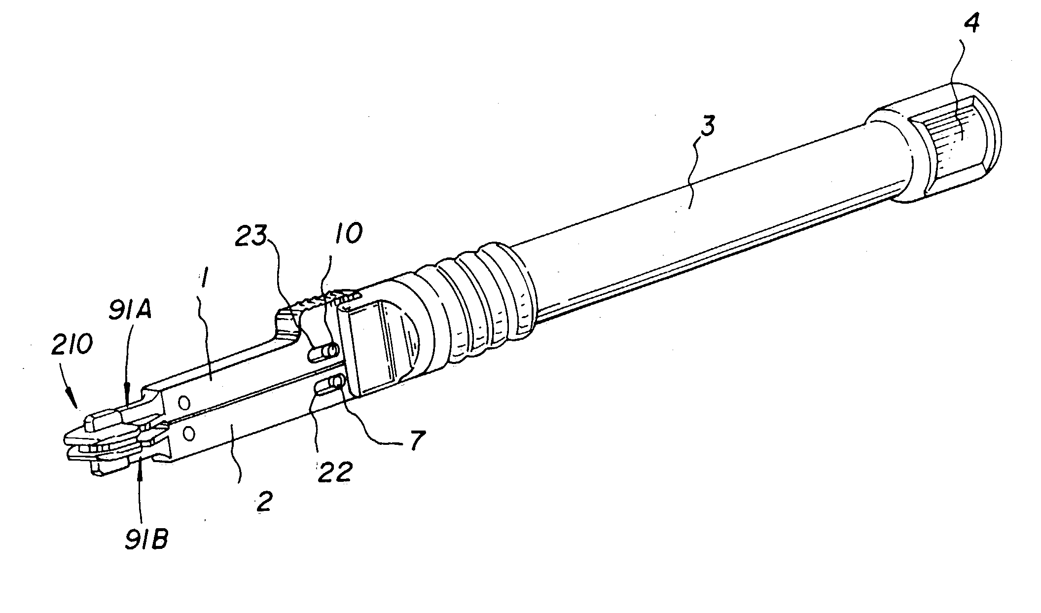
[0069]FIGS. 10-16 show an insertion instrument.

[0070] This crossed linkage instrument insertion instrument includes a body 3 having a control knob 4 at the rear end thereof and arms 1 and 2 at the forward end thereof. There is shown forward of these arms 1 and 2, the arms 91A and 91B of the insertion instrument which is shown in FIGS. 6, 7 and 8, with an assembled implant 210 being held thereby.

[0071]FIG. 11, like FIG. 10, shows the insertion instrument with the arms 1 and 2 in the closed position holding the implant 210. Referring to FIG. 11 which shows the insertion instrument in the closed position, as well as FIGS. 14 and 15 which show the insertion instrument in the opened position, it is seen that the arms 1 and 2 are operated to move towards and away from each other, or more specifically, to raise the arm 1 while the arm 2 is fixed with respect to the body 3. The mechanism for raising the arm 1 includes crossed linkage comprising a first link 5 having a pivot pin 6 at one en...

embodiment 25

[0073]FIGS. 17 and 18 illustrate another embodiment 25 of a crossed linkage insertion instrument. This insertion instrument is similar to the insertion instrument of FIGS. 10-16 with the exception of a circular knob 26 at the right hand end thereof and the thread engaging mechanism which is shown in greater detail in FIG. 18. Thus, in FIGS. 17 and 18, elements which are identical to those shown in FIGS. 10-16 are represented by the same numerals.

[0074] Referring to FIG. 18, in this case the bevel washer 14 is replaced by a tapered washer or nut 27. To the left of nut 27, the taper frictionally engages a conical wall 28 formed on the right hand end of lower arm 2. Thus, when the threaded rod 15 is caused to move to the left by the turning of knob 26, the conical portion of nut 27 frictionally engages the conical surface 28 which prevents the nut 27 from rotating, whereby the threaded rod 15 is threaded through the nut 27 to move the sleeve 13 and hence the link 11 to the left to move...

embodiment 30

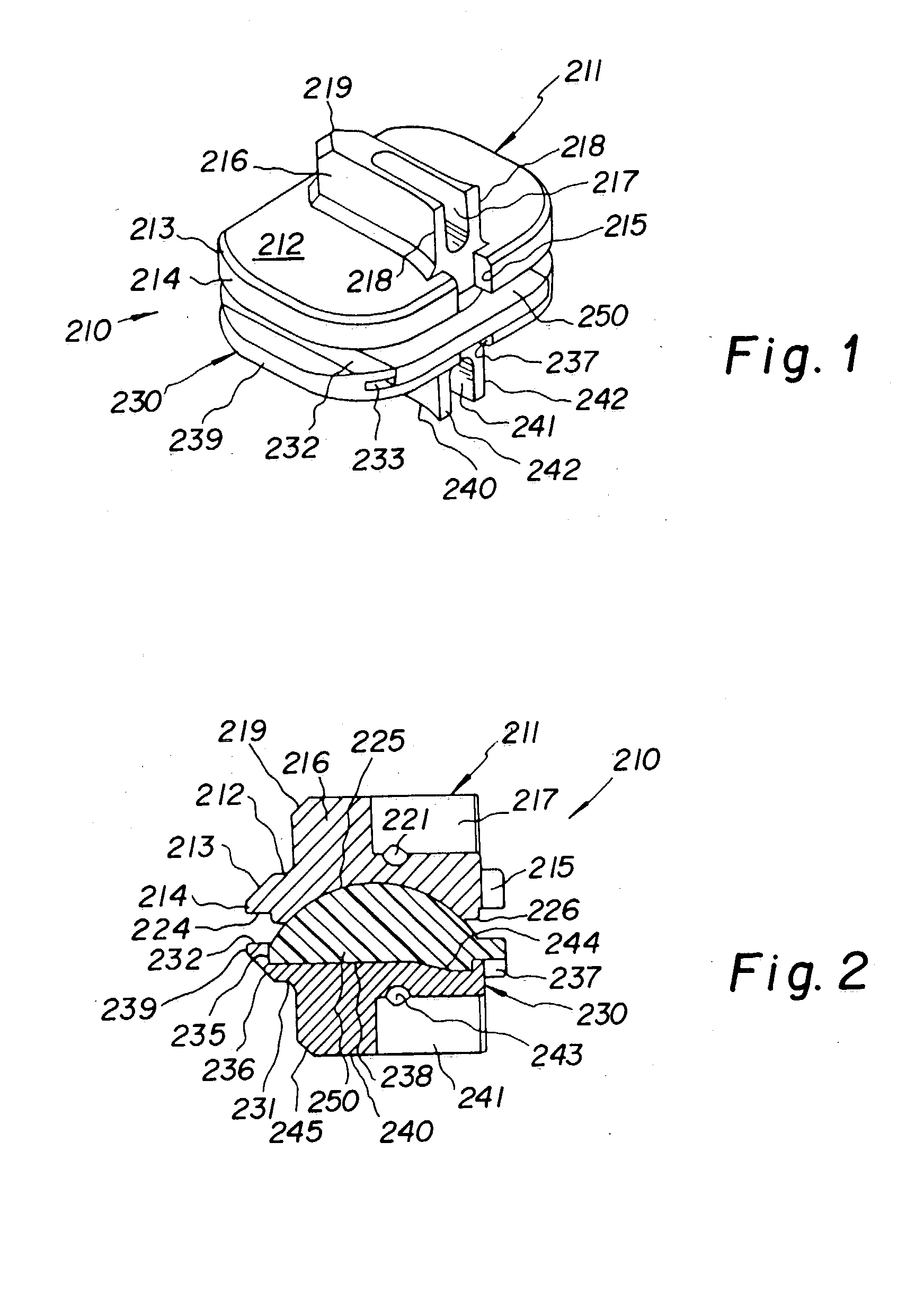
[0075]FIGS. 19-22 show another embodiment 30 of an insertion instrument. This embodiment is extremely simple and hence economical. Basically, this insertion instrument 30 comprises a plastic body 31 having a front part 32 formed integrally with body 31 and comprising upper and lower arms 33 and 34. In FIG. 19, insertion instrument 30 is shown in its closed position holding an implant 210.

[0076]FIGS. 20 and 21 illustrate the front portion 32 of the insertion instrument 30. FIG. 20 shows a thumb slide 35 and a pin 36 while in FIG. 21 part of the side wall and the thumb slide 35 are removed, thus revealing the pin 38 which would be attached to the thumb slide 35 and the rod 37 which engages a pin 36. The two arms 33 and 34 are normally urged resiliently towards each other to a closed implant holding position. However, referring to FIG. 22 by moving the rod 37 to the left, the pin 36 rides out of its recess 39 and urges the arms 33 and 34 apart, thus opening the insertion instrument.

[0...


PUM

PropertyMeasurementUnit
lengthaaaaaaaaaa
widthaaaaaaaaaa
heightaaaaaaaaaa

Abstract

Instruments and methods for inserting an intervertebral implant. Insertion of the implant is accomplished by grasping the implant between the arms of an insertion instrument having arms which separate from each other and close against each other onto the implant, such that the ends of the arms of the insertion instrument engage recesses of the implant. A spacer may be provided between the arms of the insertion instrument to help position the implant while held by the arms.

Description

FIELD OF THE INVENTION [0001] This invention relates to intervertebral implants, and more specifically, it relates to new and improved instruments and methods for inserting an intervertebral implant. BACKGROUND OF THE INVENTION [0002] Currently, when it is necessary to completely remove a disc from between adjacent vertebrae, the conventional remedy is to fuse the adjacent vertebrae together. More recently, there have been important developments in the field of disc replacement, namely disc arthroplasty, which involve the insertion of an artificial intervertebral implant into the intervertebral space between adjacent vertebrae, and which allows limited universal movement of the adjacent vertebrae with respect to each other. [0003] In conjunction with the development of such artificial intervertebral implants, instruments for inserting same were also developed. Such instruments are shown in Published Application No. WO 01 / 19295, published Mar. 22, 2001. An artificial intervertebral i...

Claims


Application Information

Patent Timeline
Patent Type & Authority Applications(United States)
IPC IPC(8): A61B17/02A61F2/00A61F2/30A61F2/44A61F2/46
CPCA61B2017/0256A61F2310/00407A61F2/4425A61F2/4611A61F2002/30383A61F2002/30616A61F2002/30649A61F2002/30884A61F2002/443A61F2002/4622A61F2002/4627A61F2002/4628A61F2220/0025A61F2310/00017A61F2310/00023A61F2310/00029A61F2310/00179A61F2/30767A61F2/46A61B17/58A61F2/30A61F2/44
Inventor MARNAY, THEIRRYBERTAGNOLI, RUDOLFMAGEE, FRANKECKHOF, STEPHANNICHOLS, DAVID L.GEISERT, CHRISTOPHE
Owner CENTINEL SPINE LLC
Why Eureka
Try Eureka