Request failover mechanism for a load balancing system

a load balancing system and request failure technology, applied in the field of network computer systems, can solve problems such as timeout failure, situation may be problematic, and inability to determine the functional status of lower-level nodes in the hierarchy

Inactive Publication Date: 2005-01-27
SUN MICROSYSTEMS INC
View PDF15 Cites 46 Cited by
  • Summary
  • Abstract
  • Description
  • Claims
  • Application Information

AI Technical Summary

Problems solved by technology

Furthermore, each load balancing node may be unable to determine the functional status of lower-level nodes in the hierarchy.
This situation may be problematic if a lower-level node undergoes a failure.
For example, requests sent to a non-functional node may not be serviced, which in turn may lead to a timeout failure.
If one or more nodes remain non-functional for an extended period of time, then a significant number of requests may go un...

Method used


Image

  • Request failover mechanism for a load balancing system
  • Request failover mechanism for a load balancing system
  • Request failover mechanism for a load balancing system

Examples


Embodiment Construction

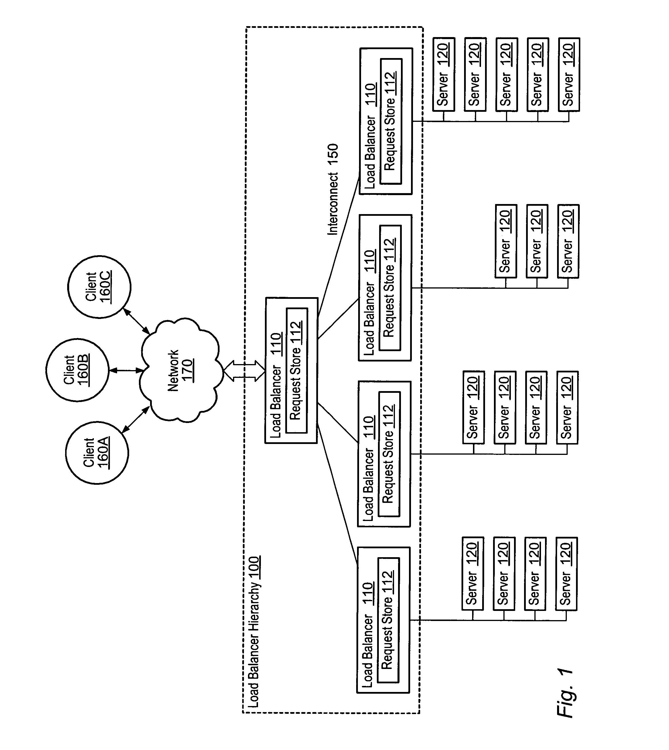
[0019] Turning now to FIG. 1, a block diagram of load balancer hierarchy 100 is shown. Load balancer hierarchy 100 is comprised of a plurality of load balancers 110 grouped into multiple levels. Load balancers 110 in load balancer hierarchy 100 are connected by interconnect 150. Likewise, each load balancer 110 at the bottom level of load balancer hierarchy 100 is connected to multiple servers 120 by interconnect 150. Load balancer hierarchy 100 is connected to clients 160A-C via network 170.

[0020] Load balancer hierarchy 100 is operable to receive requests from clients 160A -C. These requests may then be forward through the levels of the load balancer hierarchy 100 until they reach servers 120. Each load balancer 110 is operable to balance the forwarded load requests among lower-level load balancers 110 or servers 120 such that requests are distributed between lower levels in the load balancer hierarchy 100 according to a load balancing methodology. For example, requests may be lo...


PUM


Abstract

A system and method for a request failover mechanism on a load balancing system. The method may include a load balancer selecting a node from among a plurality of nodes associated with the load balancer to handle a request. The load balancer may limit selection to those nodes not known by the load balancer to be inactive. The load balancer may then determine if the selected node is able to service the request. In response to determining the selected node is unable to handle the request, the load balancer may select another node from among the plurality of nodes not known by the load balancer to be inactive. In various embodiments, the load balancer may mark nodes which are unable to service requests as inactive. The load balancer may determine if nodes are able to service requests by various methods, including active probing, passive probing, and dummy probing.

Description

BACKGROUND OF THE INVENTION [0001] 1. Field of the Invention [0002] This invention relates to the field of network computer systems and, more particularly, to a system and method for request failover on a load balancing system. [0003] 2. Description of the Related Art [0004] As workloads on modern computer systems become larger and more varied, more and more computational resources are needed. For example, a request from a client to web site may involve a load balancer, a web server, a database, and an application server. Alternatively, some large-scale scientific computations may require multiple computational nodes operating in synchronization as a kind of parallel computer. [0005] Any such collection of computational resources and / or data tied together by a data network may be referred to as a distributed system. A distributed system may be a set of identical nodes at a single location connected together by a local area network. Alternatively, the nodes may be geographically scat...

Claims


Application Information

Patent Timeline
IPC IPC(8): G06F9/46
CPCG06F9/505
Inventor SANNAPA REDDY, HARICHANDRA REDDYKOUTHARAPU, BALAJISATULOORI, SRIDHARD
Owner SUN MICROSYSTEMS INC
Why Eureka
Try Eureka