Method and assembly to prevent impact-driven manipulation of cylinder locks

a technology of cylinder locks and cylinder locks, applied in the field of common cylinder locks, can solve the problems of compromising lock security, cylinder locks are vulnerable to many methods of unauthorized manipulation, and the cylinder lock industry is a grave danger to the public, so as to prevent unauthorized manipulation of the common cylinder lock, reduce the requirements for machining tolerance and manufacturing cost, and prevent the effect of unauthorized manipulation

Inactive Publication Date: 2005-02-03
DOLEV MOSHE
View PDF17 Cites 32 Cited by
  • Summary
  • Abstract
  • Description
  • Claims
  • Application Information

AI Technical Summary

Benefits of technology

[0014] In the preferred embodiment, the modified pin assembly, containing a tumbler pin and a driver pin, is adapted so as to alter linear displacement thereof by forming a recession in one of the pins contained in the pin assembly, and an engagement means, in the other of the pins, for engaging the recession. Thus, when an impact-driven blow of a given intensity is applied so as to linearly displace the tumbler and driver pins, the pin engagement means engages the pin recession, strongly binding the tumbler and driver pins together, thereby, blocking the shear line and, consequently, preventing unauthorized manipulation of the common cylinder lock.
[0015] To ensure an optimum binding of the tumbler and driver pins together, the pin with the recession is made of a softer material than the pin with the pin engagement means. The engagement of tumbler and driver pins can be achieved by providing a flexible slotted tail section as part of the pin engagement means. In addition, the edge of the tail section is formed as a mushroom head, and the pin recession is conical in shape. These structural modifications reduce the machining tolerance requirements and the manufacturing cost, as well as ensuring optimum binding.

Problems solved by technology

Cylinder locks are vulnerable to many methods of unauthorized manipulation, prominent among them the Bumpkey and Blowgun methods.
This new development compromises lock security and poses a grave danger to the public and a challenge to the cylinder lock industry,

Method used


Image

  • Method and assembly to prevent impact-driven manipulation of cylinder locks
  • Method and assembly to prevent impact-driven manipulation of cylinder locks
  • Method and assembly to prevent impact-driven manipulation of cylinder locks

Examples


Embodiment Construction

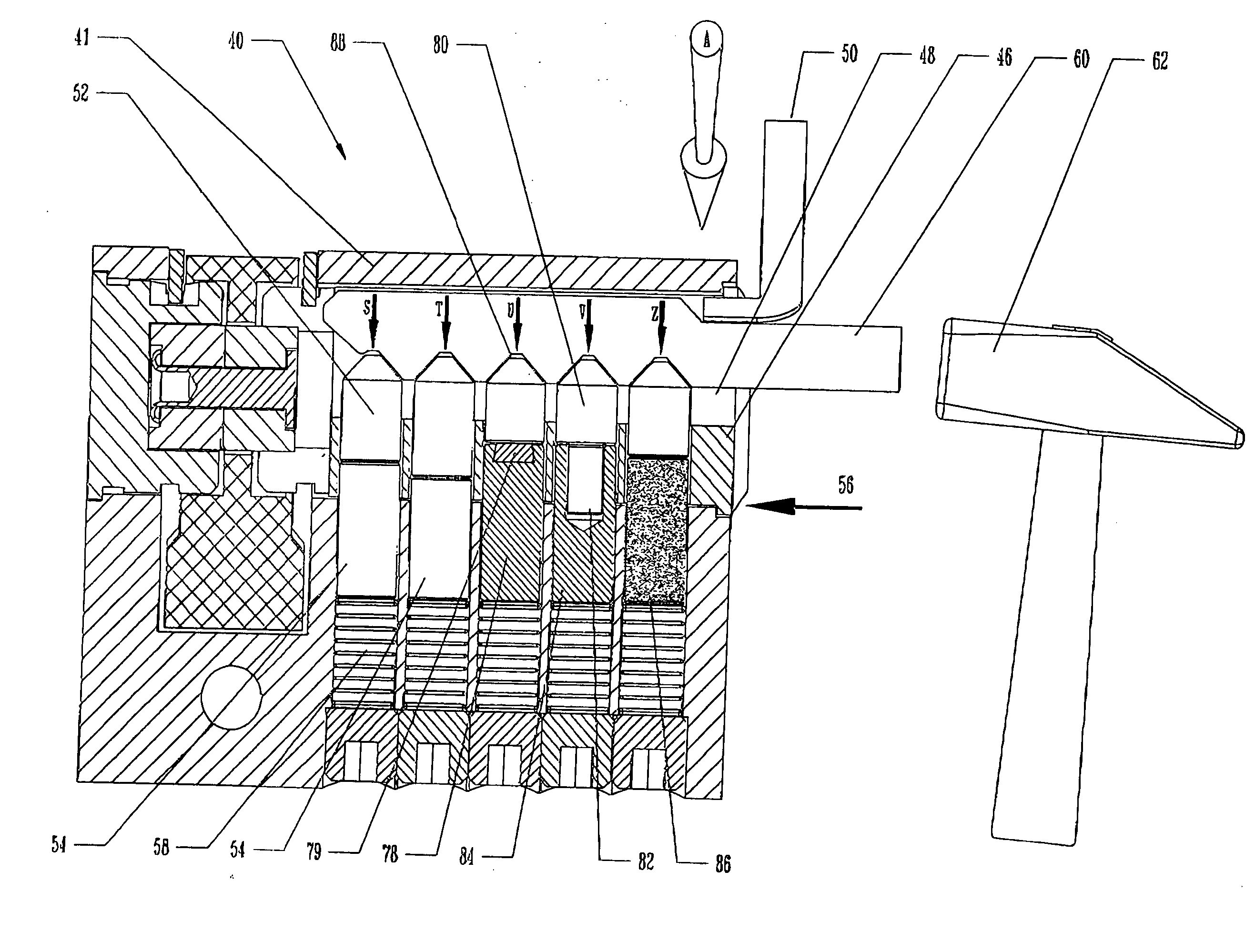
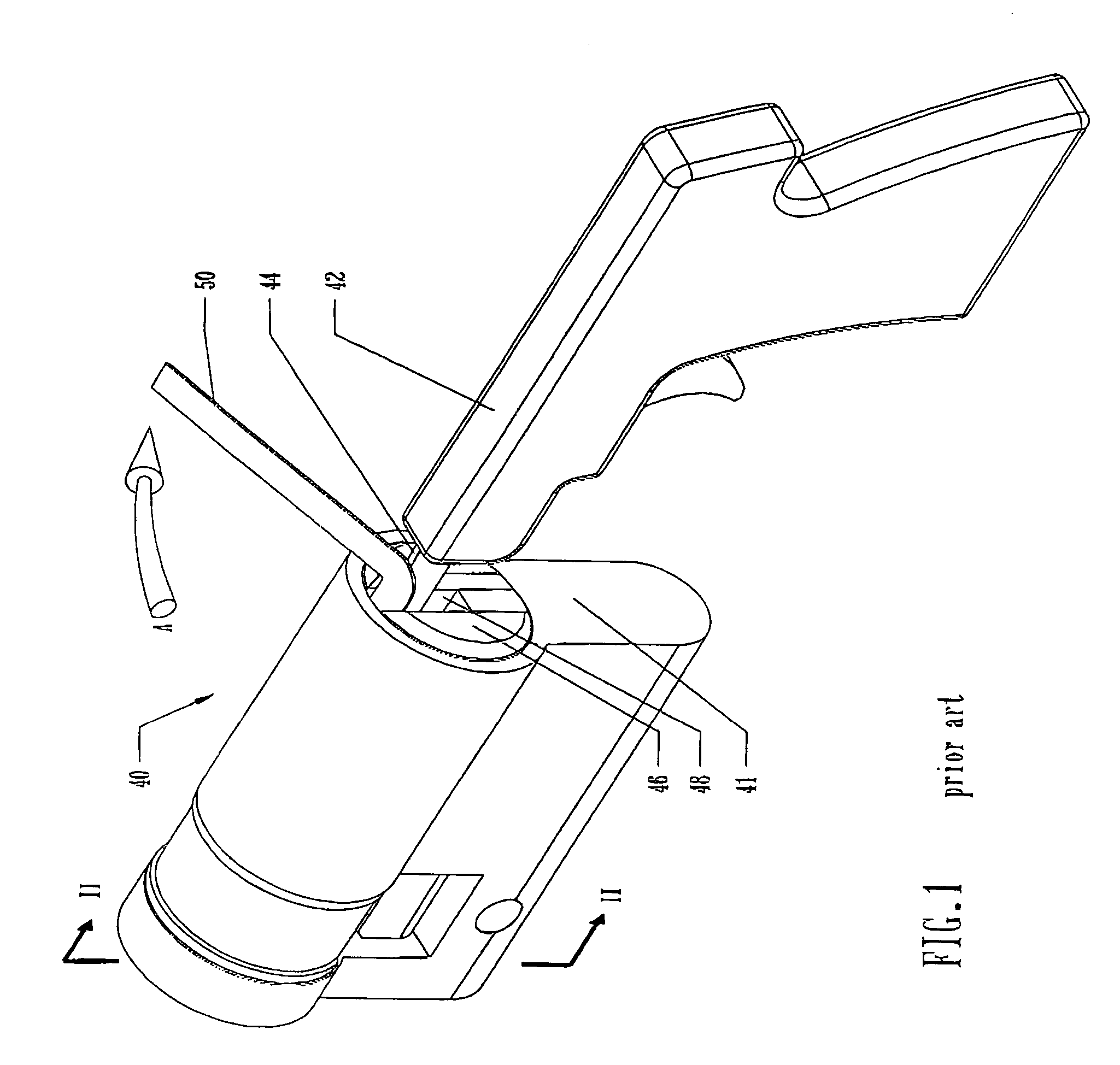
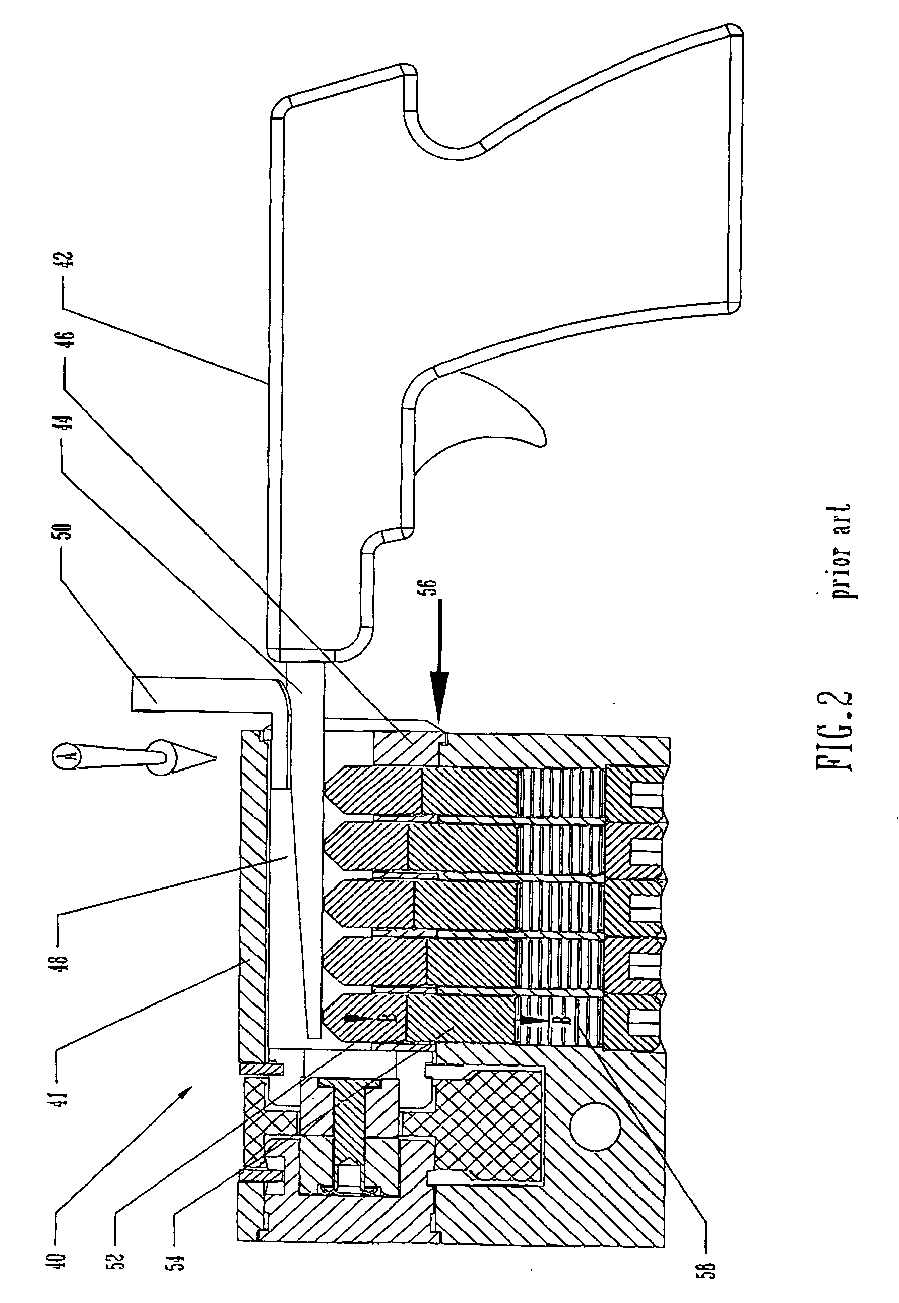
[0046] Referring to FIG. 1, there is shown a cylinder lock 40 and corresponding plug 46, constructed and operated, in accordance with the principles of a common cylinder lock. Cylinder lock 40 has a cylinder housing 41, which defines a bore, within which a plug 46 is deployed. Plug 46 defines a keyway 48. Arrow A indicates the direction of the rotational force imparted by the tension rod 50 to the plug 46.

[0047] A tool for lock manipulation, known as a Blowgun 42 has a narrow, strong metallic portion 44, which has been inserted into the keyway 48 of the lock. An associated tension rod 50 has also been positioned in the keyway 48 so as to apply rotational force to the cylinder plug 46. When an impact-driven blow is transmitted by the Blowgun 42 to the driver pins, via the tumbler pins, and they are knocked out of position, clearing the shear line, the plug then rotates slightly, due to the force exerted by the tension bar. The rotation prevents the pins from returning to their locki...


PUM


Abstract

A method and assembly for preventing unauthorized manipulation of common cylinder locks, as executed by use of the principles of the Bumpkey or Blowgun methods. The pin assembly, containing a tumbler pin and a driver pin, is adapted so as to alter linear displacement thereof, by forming a recession in one of the pins contained in the pin assembly, and an engagement means, in the other of the pins, for engaging the recession, such that when an impact-driven blow of a given intensity is applied so as to linearly displace the tumbler and driver pins, the pin engagement means engages the pin recession, strongly binding the tumbler and driver pins together, thereby, blocking the shear line and, consequently, preventing unauthorized manipulation of the common cylinder lock.

Description

FIELD OF THE INVENTION [0001] The present invention relates to common cylinder locks, which employ pins that are linearly displaceable, and more particularly, to a method and assembly for preventing unauthorized manipulation of common cylinder locks, as employed by burglars using methods based on the physical phenomenon of impact and momentum, such as the Bumpkey or Blowgun methods. BACKGROUND OF THE INVENTION [0002] The prior art of cylinder locks and their operation is based on using a key whose various features serve to displace a number of pins, arranged as pin assemblies, to predefined positions, thereby allowing the rotation of the cylinder. [0003] Cylinder locks are vulnerable to many methods of unauthorized manipulation, prominent among them the Bumpkey and Blowgun methods. These methods employ the well-known physical phenomenon of impact and momentum. [0004] A tool for lock manipulation known as a Blowgun, is comprised of a narrow, strong metallic portion that is inserted i...

Claims


Application Information

Patent Timeline
Patent Type & Authority Applications(United States)
IPC IPC(8): E05BE05B27/00E05B27/04E05B47/00
CPCE05B27/0021E05B27/0057E05B27/0071Y10S70/29E05B47/0044Y10T70/7057Y10T70/7565Y10T70/7605Y10T70/7701Y10T70/7915Y10T70/7932
Inventor DOLEV, MOSHE
Owner DOLEV MOSHE
Why Eureka
Try Eureka