Eureka AIR delivers breakthrough ideas for toughest innovation challenges, trusted by R&D personnel around the world.

Integrated check pawl, last nail-retaining, and dry fire lock-out mechanism for fastener-driving tool

Active Publication Date: 2005-02-03
STANLEY FASTENING SYST LP
View PDF67 Cites 40 Cited by
  • Summary
  • Abstract
  • Description
  • Claims
  • Application Information

AI Technical Summary

Benefits of technology

[0007] One aspect of the invention, while applicable to any power operated tool for driving headed nails from a collated supply, is particularly useful in solving the problems identified above relating to roofing tools. The tools contemplated herein operate so that the leading nail of the supply is fed along a feed track into a drive track by a power operated reciprocating mechanism so as to enable the leading nail on the drive track to be driven outwardly of the drive track into a workpiece by the power system of the tool. In this aspect of the invention, the reciprocating mechanism includes an integrated function member which has a check pawl portion and either a last-fastener-retaining portion or a dry fire lock out portion or both. The configuration of the check pawl portion of the integrated function member is such that during operation of the power operated tool when two or more headed nails remain in the supply to be driven, the check pawl portion of the integrated function member engages the succession of headed nails within the fastener feed track to limit the succession of headed roofing nails from moving as the reciprocating mechanism retracts while operating to advance the succession of headed nails toward the drive track. The integrated function of the last-fastener-retaining portion is such that when a last headed nail remains to be driven into the workpiece, the last-fastener retaining portion holds the headed nail within the drive track to prevent the last headed nail from falling out of the drive track without being driven into the workpiece. The integrated function of the dry fire lock out portion of the integrated function member is such that when no headed nails remain within the tool, the dry fire lockout portion prevents operation of the actuating mechanism for the power system of the tool to thereby prevent further fastener driving movement of the fastener driving member.
[0009] Still another aspect of the present invention relates to an improved method for retaining the last headed fastener within the fastener drive track of a fastener driving tool so as to prevent the last headed fastener from falling out of the drive track without being driven by the operation of the tool. The method includes the step of engaging the head of the last fastener in the drive track along a periphery thereof with a first head engaging surface at a position disposed laterally with respect to the predetermined direction of movement of the last headed fastener into the drive track and applying a force on the head of the last fastener by the engagement of said first surface which causes the head of the last nail to be biased into engagement with a wall surface defining a portion of the drive track which is laterally opposite from the position of engagement of said first surface so that the head of the last nail is gripped between said two opposed surfaces.

Problems solved by technology

Because the nails are arranged in a spiral or coil configuration, a spring-biased or otherwise tensioned pusher apparatus by means of which the supply of nails is urged toward the fastener-driving track from the tail end of the supply would not be suitable.
However, such a device has not proven to be very effective and reliable during extensive field usage.
That is undesirable because the operator will have to clean up after the job, he may injure himself by stepping on the dropped nails, and / or it is wasteful of nails.
In addition to these drawbacks or disadvantages, some fastener-driving tools are known in which there is no effective mechanism to indicate to the operator that no fasteners (e.g., nails) remain in the tool.
In that case, the operator can keep operating the tool without fasteners, which causes the tool driver tip to strike and dent the roofing shingle or other workpiece.

Method used


Image

  • Integrated check pawl, last nail-retaining, and dry fire lock-out mechanism for fastener-driving tool
  • Integrated check pawl, last nail-retaining, and dry fire lock-out mechanism for fastener-driving tool
  • Integrated check pawl, last nail-retaining, and dry fire lock-out mechanism for fastener-driving tool

Examples


Embodiment Construction

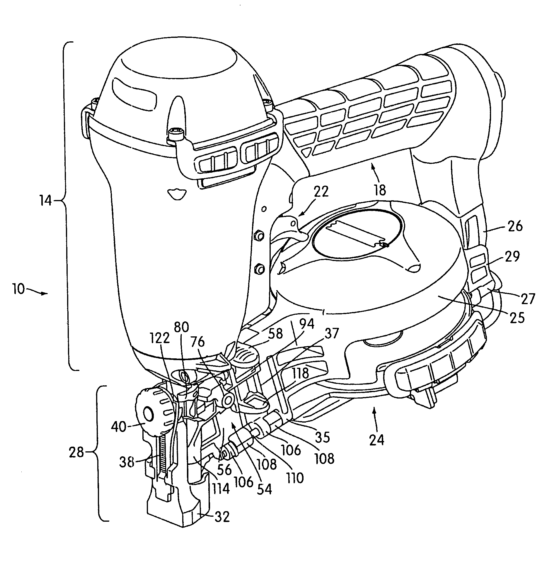
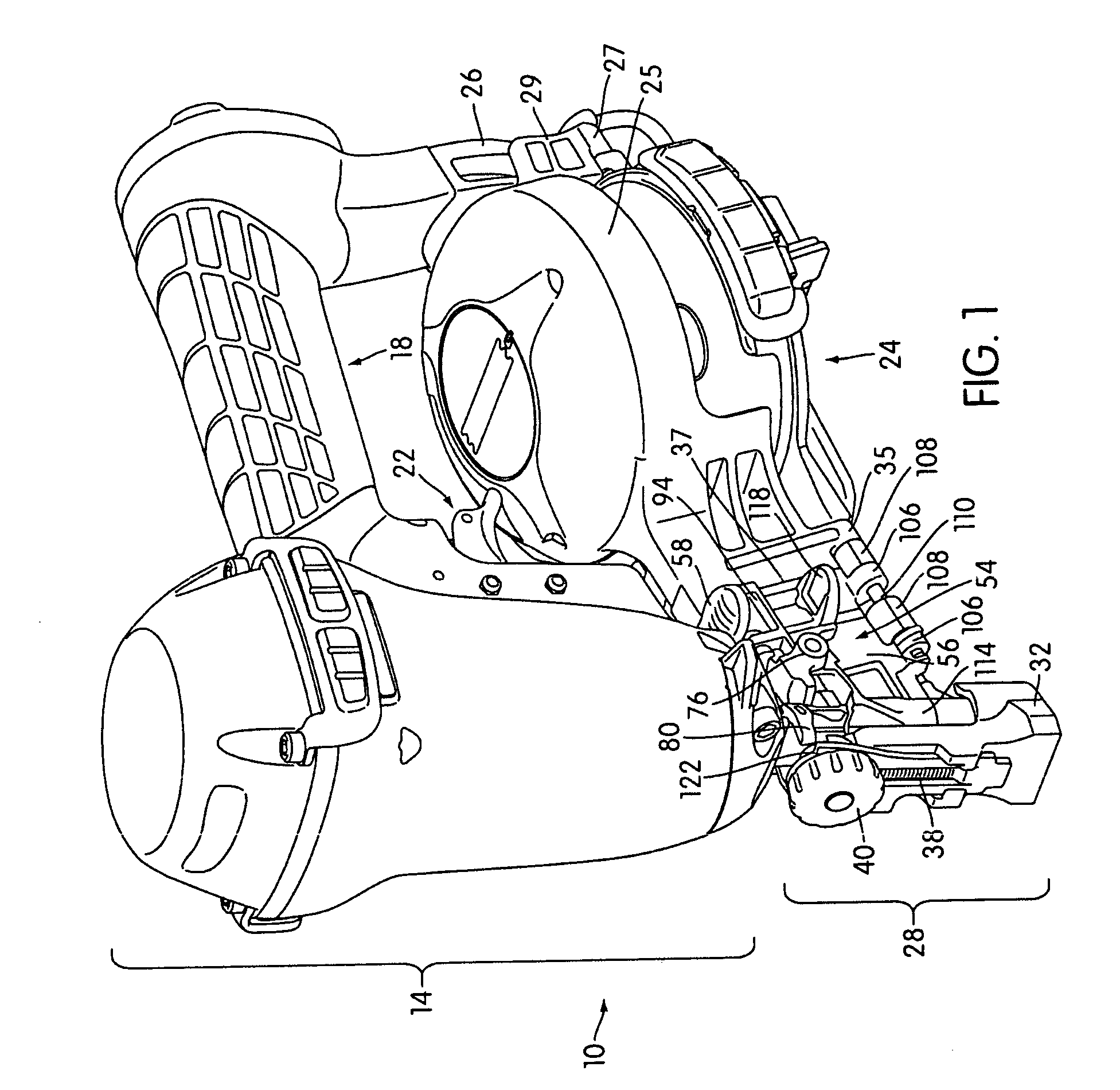
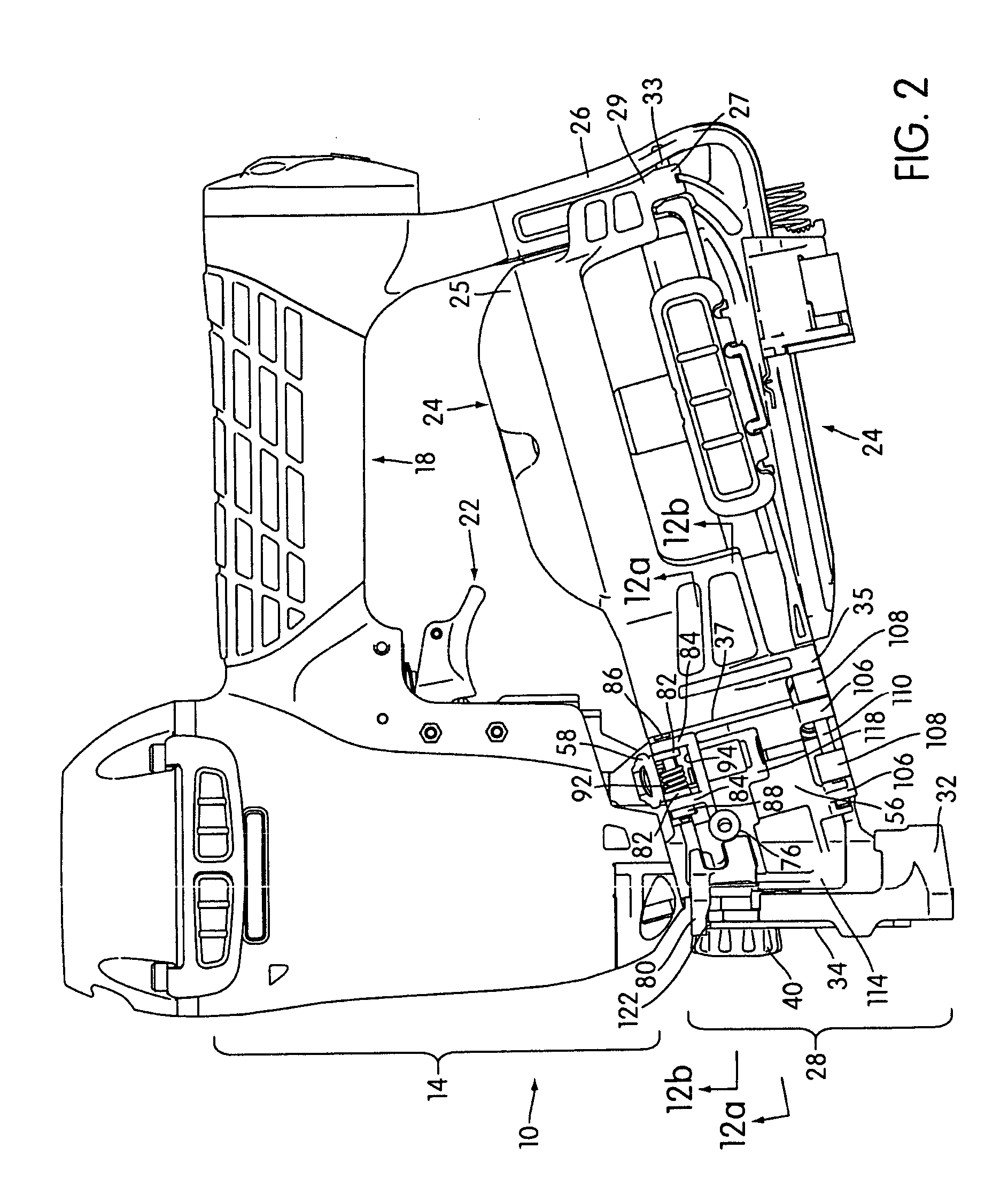
[0022] The overall arrangement of a roofing tool 10 according to the invention is illustrated in FIGS. 1-4. The roofing tool 10 has a nail-driving member 12 that is located within a main body portion 14 of the roofing tool 10. The nail-driving member 12 may, for example, be pneumatically actuated to drive nails 16 or other fasteners into a workpiece, as is known in the art. A handle portion 18 extends from the main body portion 14 and allows the roofing tool 10 to be manually manipulated. The handle portion 18 includes a thread-type connection 20 by means of which a compressor air hose is connected to the roofing tool 10 to provide high pressure air to the roofing tool 10 to operate it. The roofing tool 10 further includes a trigger mechanism 22 constituting one part of an actuating mechanism or means by which the roofing tool is actuated to drive nails 16 or other fasteners into the workpiece.

[0023] The roofing tool 10 further includes a magazine assembly including a magazine port...


PUM

PropertyMeasurementUnit
Flexibilityaaaaaaaaaa
Shapeaaaaaaaaaa
Distanceaaaaaaaaaa

Abstract

A fastener-driving tool includes an integrated function member that performs at least two of the following three functions: a check pawl function, a last fastener-retaining function, and a dry fire lock-out function. In the disclosed embodiment, the integrated function member is provided as a lever-type structure that constitutes part of the access door assembly by means of which access is gained to the fastener drive track along which fasteners (e.g., roofing nails) are fed to the driving portion of the tool. Also disclosed is an improved method of retaining the last nail in the drive track by a lateral head gripping action and a tool for performing the method.

Description

1. FIELD OF THE INVENTION [0001] In general, the present invention relates to a fastener-driving tool such as, but not limited to, a pneumatic nail driver. More particularly, the invention relates to mechanism by means of which fasteners are fed to the fastener drive track and retained within the drive track, and by means of which dry firing of the tool is prevented. 2. BACKGROUND OF THE INVENTION [0002] Roofing tools (e.g., pneumatic roofing tools) are used to drive roofing nails into workpieces such as shingles to secure the shingles to the underlying wood substructure. Such roofing tools typically have a magazine that holds a supply of nails. The nails are typically collated by being spot-welded or otherwise affixed at their shanks to a pair of flexible metal wires or by being embedded in or adhered to a plastic or paper collating strip. Existing nail magazines typically are configured to receive a supply of nails arranged in either a stick or a coil arrangement. [0003] Because t...

Claims


Application Information

Patent Timeline
IPC IPC(8): B25C1/00B25C5/16
CPCB25C1/003B25C5/1627B25C1/008
Inventor JALBERT, DAVID B.HEWITT, CHARLES W.FANG, ZHENG
Owner STANLEY FASTENING SYST LP
Why Eureka
Eureka Blog
Learn More