Display driver and method for driving an emissive video display

a technology of emissive light and video display, which is applied in the direction of color television details, television systems, instruments, etc., can solve the problems of reducing the convenience and portability of the device, increasing the size and weight of the portable device, and consuming little power of the display

Inactive Publication Date: 2005-02-03
FUNSTON DAVID L
View PDF15 Cites 43 Cited by
  • Summary
  • Abstract
  • Description
  • Claims
  • Application Information

AI Technical Summary

Problems solved by technology

Because these displays are often in use, it is necessary that these displays consume little power.
This increases the size and weight of the portable device, typically reducing the convenience and portability of the device.
However, the video displays of the prior art have consumed too much power to permit such video displays to be operated continuously.
The prior art has not provided a display driver or method for operating an OLED that is efficient enough to permit the near continuous operation of the OLED for the purposes of sustaining status displays.
It will be appreciated that incorporating such a dual display scheme into a portable electronic devices increases the number of components of the device, the cost of designing the device, and the size and weight of the device.
These factors increase the cost of portable electronic devices that incorporate both video and separate LED or LCD status displays.
The main limitation of this solution is that it is expensive to design and manufacture such an OLED.
Accordingly, a display device designed for one product in accordance with the '704 patent will not be readily adaptable for use in a second product.
Thus, the forgoing needs are not met by the prior art.

Method used


Image

  • Display driver and method for driving an emissive video display
  • Display driver and method for driving an emissive video display
  • Display driver and method for driving an emissive video display

Examples


Embodiment Construction

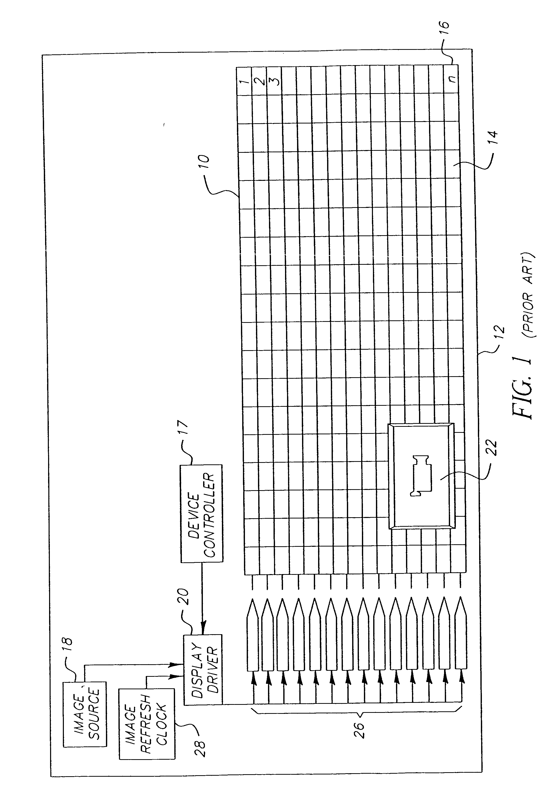
[0024]FIG. 1 shows an ELD 10 operated by a display driver 20 according to the method of the prior art. Display 10 is fixed in device 12. In this example, ELD 10 comprises an OLED having light emitting elements 14 that are organized into a vertical array of “n” horizontal rows 16. Each horizontal row 16 is associated with one of a plurality of row drivers 26. A device controller 17 controls display 10, an image source 18, and display driver 20. Image source 18 provides illumination values to the display driver 20. Image source 18 provides an image to display driver 20. Display driver 20 receives the image and transmits illumination values to row drivers 26 as shown in FIG. 1, or directly to elements 14. Where row drivers 26 are used, each row driver 26 received illumination values from display driver 20 and causes the elements 14 in the associated horizontal row 16 to illuminate at intensity levels that are characteristic of the illumination values. Image 22 appears on ELD 10 as a co...


PUM


Abstract

Methods and control systems are provided for displaying an image electronically encoded in the form of illumination values using a two-dimensional matrix of image elements, each element adapted to covert energy to emit the light when an illumination value is written thereto. In accordance with one method, an array of elements including less than all of the elements in the matrix are defined to display the image so that the amount of energy consumed by the elements of the matrix when displaying an image using the elements of the array is lower than the amount of energy that the elements of the matrix would consume in displaying the image using all of the elements of the matrix.

Description

CROSS-REFERENCE TO RELATED APPLICATIONS [0001] This is a continuation of application Ser. No. 09 / 848,067, filed May 3, 2001.FIELD OF THE INVENTION [0002] The present invention relates to a display driver and method for operating an emissive light video display. BACKGROUND OF THE INVENTION [0003] Status displays are an important feature of electronic devices such as cellular telephones, global positioning systems (GPS), CD players, video cameras, digital cameras, conventional cameras, hybrid cameras and other devices. Status displays are used to inform the user of such a device about conditions that may impact the operation of the device. Examples of status displays include displays that indicate cellular telephone signal strength, battery status, and other warnings. These displays are typically active whenever the device is active. Because these displays are often in use, it is necessary that these displays consume little power. [0004] In the prior art, it is known to use Light Emit...

Claims


Application Information

Patent Timeline
Patent Type & Authority Applications(United States)
IPC IPC(8): H04N5/66G09G3/20G09G3/30G09G3/32H04N5/70
CPCG09G3/32G09G2330/021G09G2310/04G09G2310/0259
Inventor FUNSTON, DAVID L.
Owner FUNSTON DAVID L
Why Eureka
Try Eureka