Ink cartridge, detection device for cartridge identification and ink level detection, and image formation apparatus comprising thereof

a detection device and cartridge technology, applied in the field ofink cartridges, can solve the problems of failure of image formation, error detection of ink level, etc., and achieve the effect of reducing the level of the cartridg

Inactive Publication Date: 2005-02-03
BROTHER KOGYO KK
View PDF12 Cites 81 Cited by
  • Summary
  • Abstract
  • Description
  • Claims
  • Application Information

AI Technical Summary

Benefits of technology

[0051] In the image formation apparatus constituted as above, a position spaced out from the preset boundary for the predetermined distance in the first direction, which is along the passage direction, is set to be the first detection position, and a position spaced out from the preset boundary for the predetermined distance in the second direction opposite to the first direction is set to be the second detection position. By setting the predetermined distance from the preset boundary shorter than the width (the length along the passage direction) of the first detection target portion, the detector can detect the first detection target portion without failure. Moreover, by setting the predetermined distance from the preset boundary shorter than the width of the second detection target portion, the detector can detect the second detection target portion without fail.
[0052] The corrector can be arrange to set the first and second detection target portions as a new first detection target portion and correct the first detection position, if the amount of the light received by the light receiver of the detector does not change more greatly than the predetermined level, while the detector is moved by the transporter relatively so as to pass through the area including at least the first and second detection positions. This arrangement can enlarge the area of the first detection target portion, and correct the first detection position in a wider area for reliable detection. Thus, ink level detection can be more accurately conducted.

Problems solved by technology

An error detection of ink amount can cause a failure in image formation due to a shortage of ink.
Error detection of ink level and failure in image formation can be inhibited by this kind of ink cartridge.

Method used


Image

  • Ink cartridge, detection device for cartridge identification and ink level detection, and image formation apparatus comprising thereof
  • Ink cartridge, detection device for cartridge identification and ink level detection, and image formation apparatus comprising thereof
  • Ink cartridge, detection device for cartridge identification and ink level detection, and image formation apparatus comprising thereof

Examples


Embodiment Construction

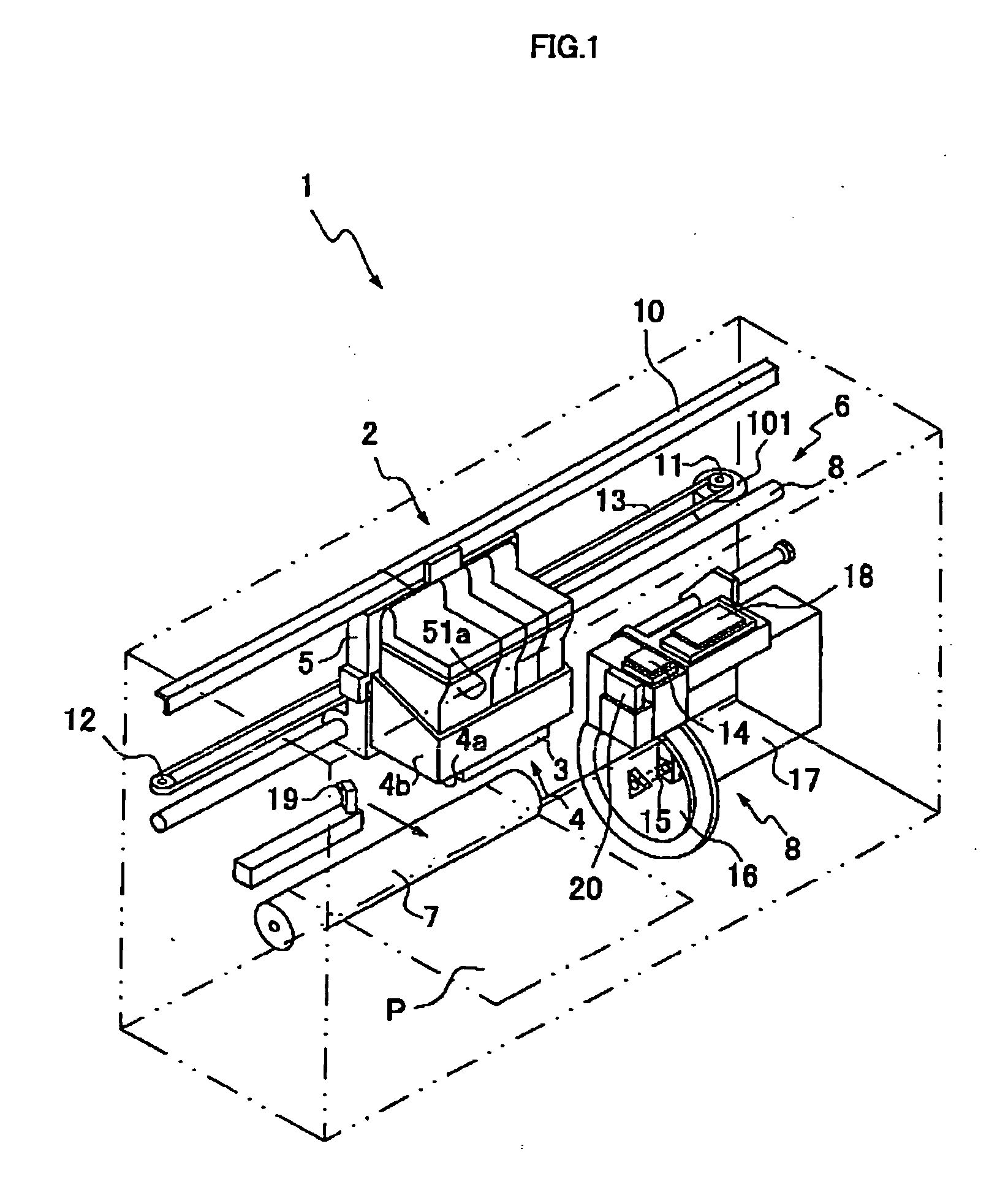
[0079] The following describes an inkjet recording apparatus as an example of an image forming apparatus.

[0080] Referring to FIG. 1, the inkjet recording apparatus 1 comprises a head unit 4 having a printing head 5 which is an ink head to form an image on a recording medium P such as paper, a carriage 5 mounting ink cartridges 2 and the head unit 4 thereon, a drive unit 6 which reciprocates the carriage 5 in a straight direction, a platen roller 7 extending in the direction of the reciprocating movement of the carriage 5 and facing the printing head 3, a purge unit 8 and an optical sensor 19 which serves as a detector (to be described later). In the present embodiment, the optical sensor 19 is fixed inside the inkjet recording apparatus 1. Three partitions (not shown) are disposed on a loading portion 4a of the head unit 4. Between a pair of side covers 4b formed on both sides of the loading portion 4a, the loading portion 4a is sectioned into four mounting portions by the partitio...


PUM


Abstract

The ink cartridge has a first detection target portion for detecting ink level and a second detection target portion for identifying the type of an ink cartridge. The ink level detection device uses an optical sensor to scan the first and second detection target portions of the ink cartridge, and detects ink level and the type of the ink cartridge, that is, whether the ink cartridge is containing standard amount of ink or large amount of ink. Therefore, the number of image formation on recording media can be estimated, and failure in image formation due to a shortage of ink in the middle of image formation can be inhibited.

Description

BACKGROUND OF THE INVENTION [0001] (1) Field of the Invention [0002] This invention relates to an ink cartridge used for image forming apparatus such as a printer, a copier and a facsimile. This invention also relates to a detection device for identification of an ink cartridge, and to an image forming apparatus comprising the ink cartridge and the detection device. [0003] (2) Background Art [0004] Amongst conventional ink cartridges used for an inkjet recording apparatus, some of them are constituted to allow ink level detection by optical devices. [0005] Generally, ink of this type of ink cartridge is reserved in a case having an optically transparent portion. Light is emitted from a light source to inside the case through the transparent portion. The amount of reflected light changes depending whether or not ink is remained in the ink cartridge. The presence of ink is detected by this system. Yoshiyama et al (Japanese Patent Publication No. 2002-292890), for example, discloses th...

Claims


Application Information

Patent Timeline
Patent Type & Authority Applications(United States)
IPC IPC(8): B41J2/175
CPCB41J2/17566
Inventor HAYAMIZU, KAZUHIROYAMADA, MASATOSHISAWAKI, YUKICHIAKAGI, KOJI
Owner BROTHER KOGYO KK
Why Eureka
Try Eureka