Microscope control apparatus, microscope apparatus and objective lens for microscope

a technology of microscope and control apparatus, which is applied in the direction of microscopes, instruments, optics, etc., can solve the problems of significant deterioration of observation efficiency

Inactive Publication Date: 2005-02-03
NIKON CORP
View PDF5 Cites 44 Cited by
  • Summary
  • Abstract
  • Description
  • Claims
  • Application Information

AI Technical Summary

Benefits of technology

[0018] According to the present invention as described above, a microscope control apparatus that enables expeditious aberration correction in accordance with a change in the observation condition can is realized.

Problems solved by technology

However, if a complex operation of determining the optimum position of the aberration correction lens is to be performed every time a change in the observation condition occurs, the efficiency of observation will be deteriorated significantly.

Method used


Image

  • Microscope control apparatus, microscope apparatus and objective lens for microscope
  • Microscope control apparatus, microscope apparatus and objective lens for microscope
  • Microscope control apparatus, microscope apparatus and objective lens for microscope

Examples


first embodiment

[0031] [First Embodiment]

[0032] A first embodiment of the present invention will be described with reference to FIGS. 1, 2, 3, 4, 5 and 6.

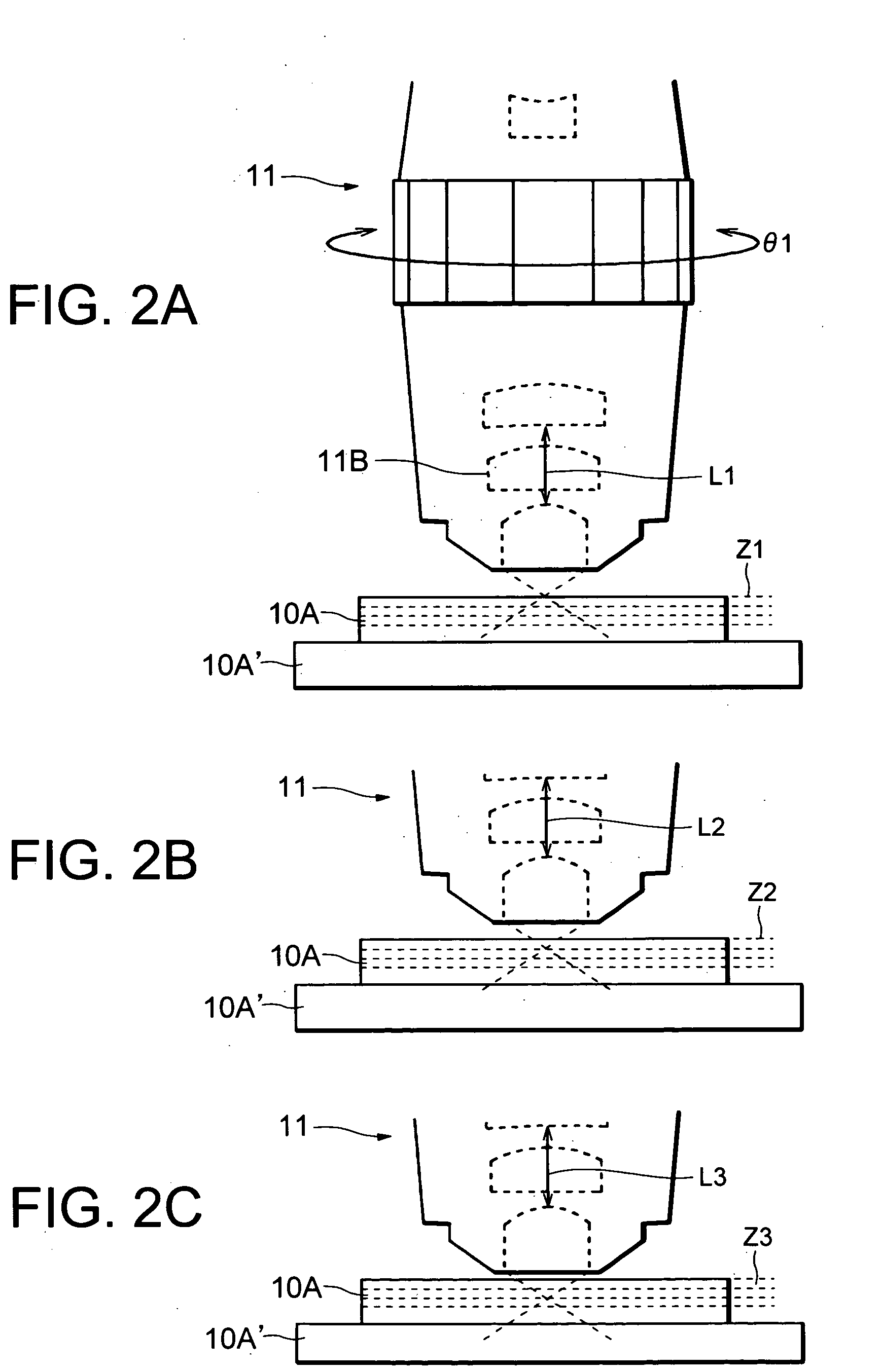
[0033] This embodiment is directed to a microscope system in which the present invention is applied. Here, a description will be made with reference to a case in which a three-dimensional image of an object to be observed (i.e. a specimen 10A) is obtained.

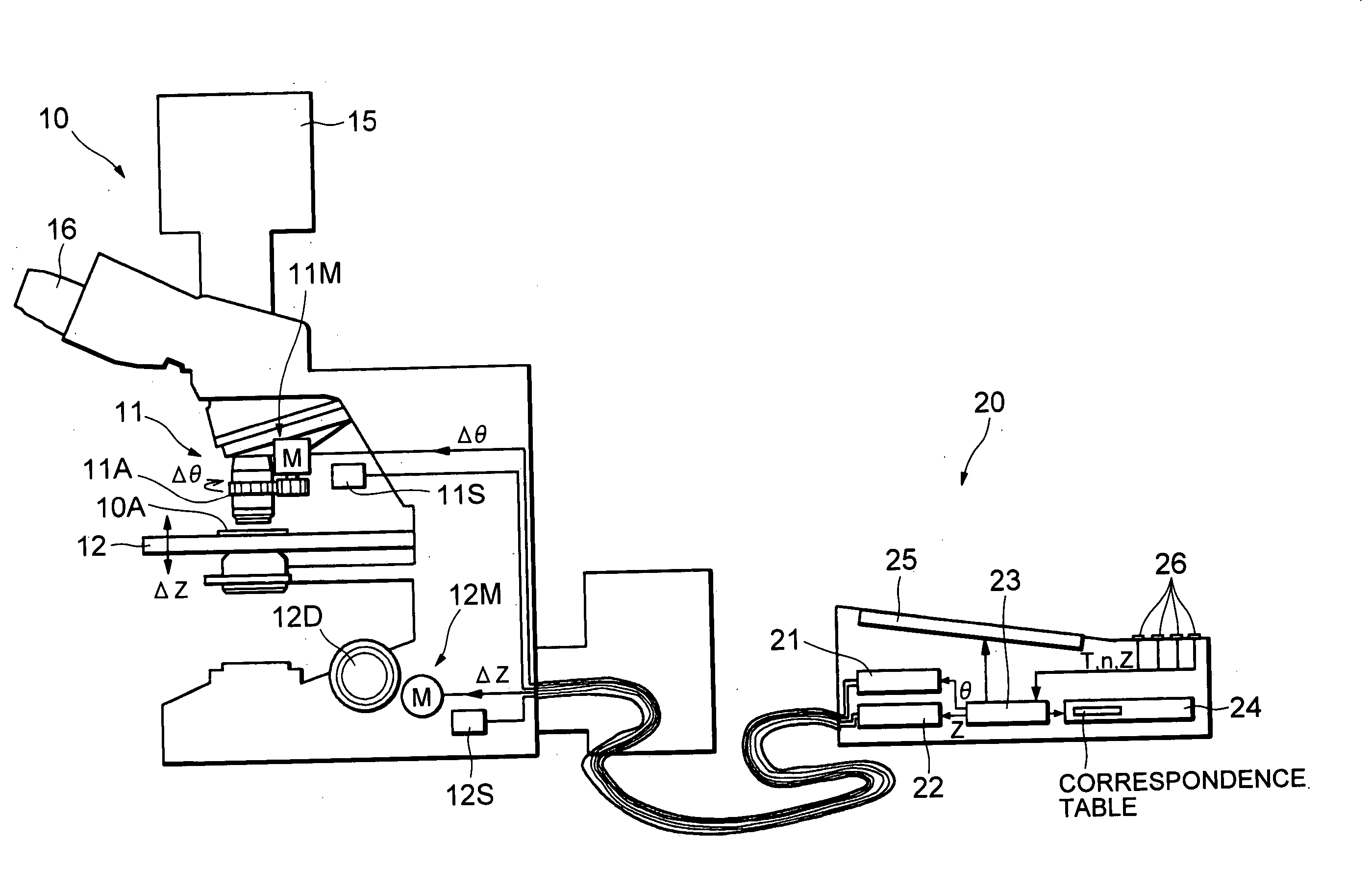
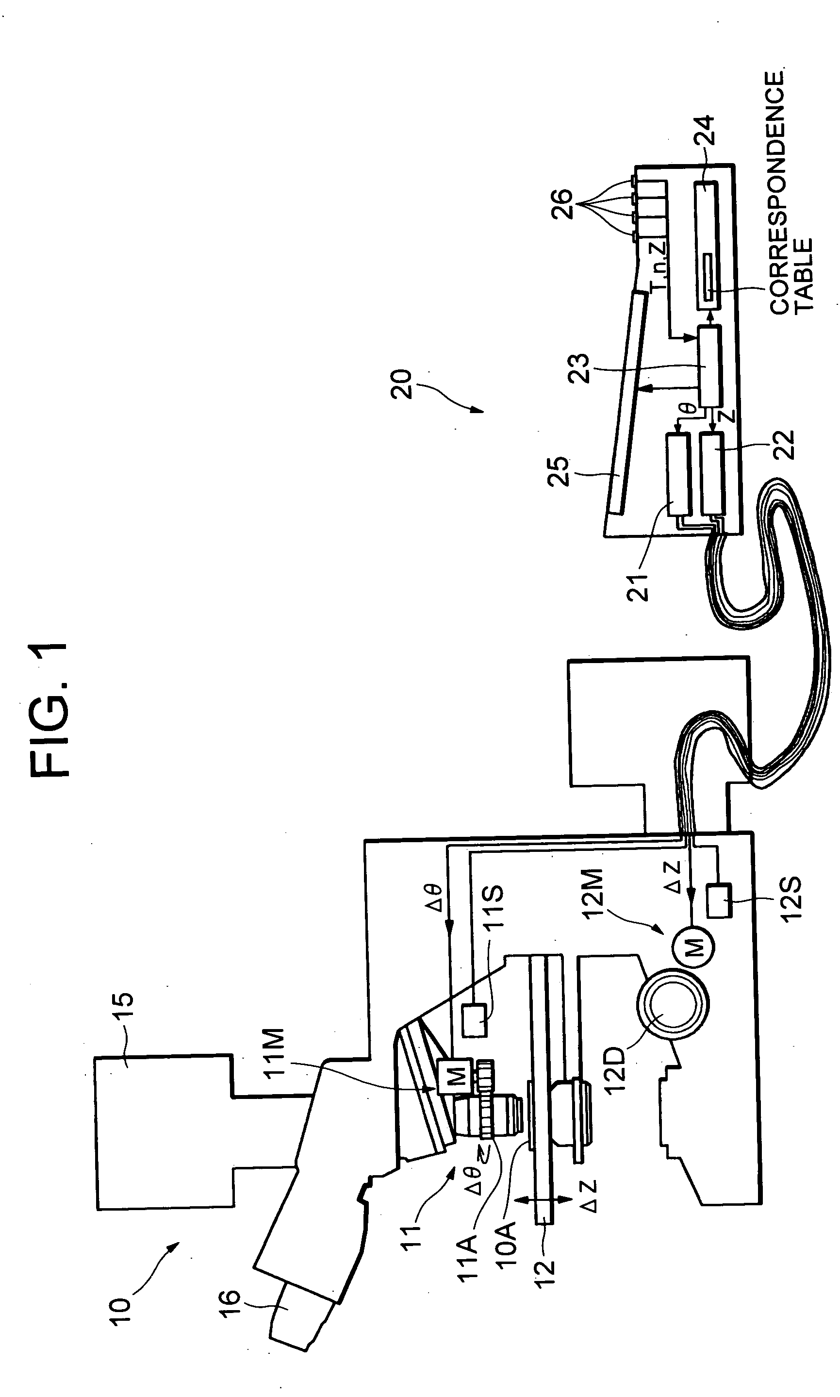
[0034] Referring to FIG. 1, the microscope system of this embodiment includes a microscope apparatus 10 and a controller 20 connected with the microscope apparatus 10 via a cable or the like. In the following, the microscope apparatus 10 and the controller 20 will be described in the mentioned order.

[0035] The microscope apparatus 10 is provided with a microscope objective lens 11, a stage 12, a camera 15, an eyepiece lens 16, a focus adjustment apparatus and an illumination apparatus.

[0036] The stage 12 is driven by an electromotive stage driving mechanism 12M composed of a force transmissio...

second embodiment

[0124] [Second Embodiment]

[0125] The second embodiment of the present invention will be described with reference to FIG. 7.

[0126] This embodiment is directed to a method for measuring the refractive index n of a specimen 10A using a microscope system.

[0127] The microscope system used in this embodiment is similar to the microscope system according to the first embodiment but partly modified in such a way as to enable measurement of the refractive index.

[0128] As shown in FIG. 7, the microscope apparatus 10 in the microscope system of this embodiment is provided with a sensor 10S disposed in the vicinity of the specimen 10A for measuring the temperature of the specimen 10A.

[0129] A detection signal output from the sensor 10S is supplied to a CPU 23 in the controller 20.

[0130] The rotational position of a correction ring 11A and set position of a stage 12 along the optical axis direction (i.e. the Z direction) can be changed manually. (In connection with this, reference sign 12D ...


PUM


Abstract

A microscope control apparatus is used with a microscope apparatus attached with a microscope objective lens having an aberration correction lens. The microscope control apparatus includes a memory in which information on driving amounts of the aberration correction lens that are optimum for various observation conditions respectively, entry device for allowing an observer to enter a single parameter or multiple parameters for specifying an observation condition set upon observation, and calculation device for determining a driving amount of the aberration correction lens that is optimum for the observation condition specified by the parameter(s) based on the information.

Description

[0001] This application claims the benefit of Japanese Patent application No. 2003-202503 which is hereby incorporated by reference. BACKGROUND OF THE INVENTION [0002] 1. Field of the Invention [0003] The present invention relates to a microscope control apparatus, a microscope apparatus and an objective lens of a microscope. [0004] 2. Related Background Art [0005] Some kinds of objective lenses of a microscope is provided with an aberration correction lens that can move in the optical axis direction (see, for example, Japanese Patent Application Laid-Open No. 2002-169101). [0006] With a change in the thickness and refractive index of a cover glass for protecting the surface of a specimen upon, for example, replacement of the cover glass, the state of aberrations changes. In such a case, a new position (i.e. an optimum position) of an aberration correction lens at which the aberrations are made minimum (in other words, at which an image of the specimen can be clearly observed) is de...

Claims


Application Information

Patent Timeline
Patent Type & Authority Applications(United States)
IPC IPC(8): G02B21/00G02B21/02G02B21/24G02B21/36G02B27/00
CPCG02B27/0025G02B21/361
Inventor SASE, ICHIROWATANABE, KATSUYA
Owner NIKON CORP
Why Eureka
Try Eureka