Dimmable rearview assembly having a glare sensor

a rearview assembly and glare sensor technology, applied in the direction of optical radiation measurement, photometry using electric radiation detectors, instruments, etc., can solve the problems of compromising the electrical design, adding the cost of additional parts and assembly processes, and undetectable low optical gain

a rearview assembly and glare sensor technology, applied in the direction of optical radiation measurement, photometry using electric radiation detectors, instruments, etc., can solve the problems of compromising the electrical design, adding the cost of additional parts and assembly processes, and undetectable low optical gain

US20050024729A1Inactive Publication Date: 2005-02-03GENTEX CORP

Image

  • Dimmable rearview assembly having a glare sensor
  • Dimmable rearview assembly having a glare sensor
  • Dimmable rearview assembly having a glare sensor

Examples


Embodiment Construction

[0089] Reference will now be made in detail to the present preferred embodiment of the invention, an example of which is illustrated in the accompanying drawings. Wherever possible, the same reference numerals will be used throughout the drawings to refer to the same or like parts.

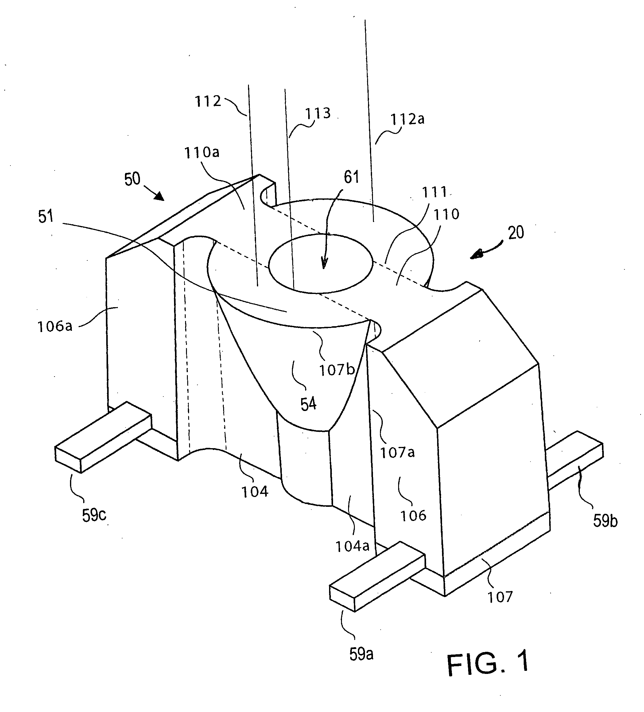
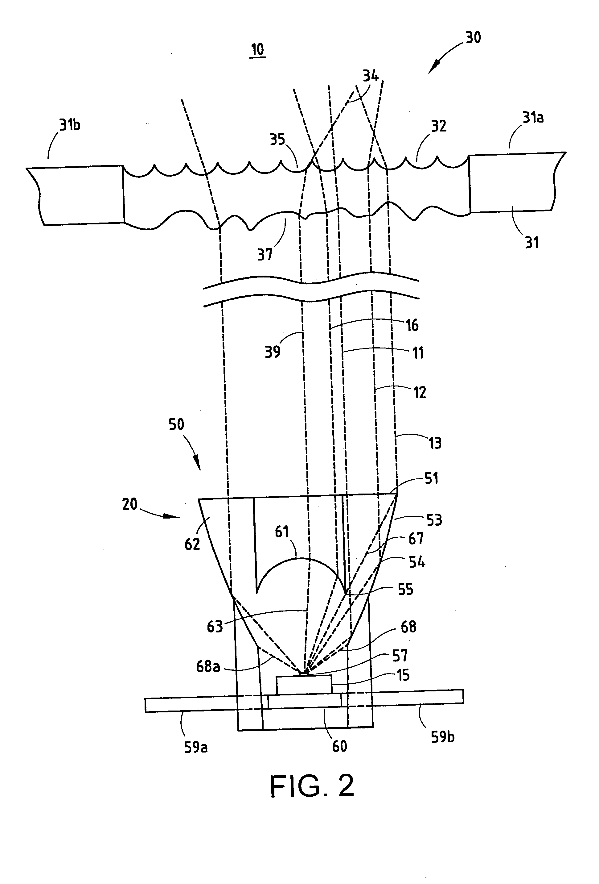
[0090] A sensor device 50 that is constructed in accordance with one embodiment of the present invention is shown in FIG. 1. A sensor subassembly 10 incorporating sensor device 50 is shown in FIG. 2. The sensor device 50 includes a support structure, such as a printed circuit board or a lead frame 60, an integrated sensing circuit 15 having an active sensing area 57 mounted on the support substrate for sensing optical radiation, preferably visible light, and an encapsulant 62 encapsulating the sensing circuit on the support structure. In general, the encapsulant 62 defines a lens structure 20 including an integral refracting lens portion 61 preferably having an elliptical refracting surface for focusing i...


PUM


Abstract

A rearview assembly of the present invention may include a housing adapted to be mounted to the vehicle, a rearview element disposed in the housing for providing an image to the driver of the rearward view from the vehicle, and a glare sensor positioned to receive light from passing through the rearview element. The glare sensor may be a surface-mounted to a circuit board. An optional secondary optical element may be disposed between the rearview element and the glare sensor. The optional secondary optical element may have an anamorphic lens for providing different fields of view horizontally versus vertically.

Description

CROSS-REFERENCE TO RELATED APPLICATIONS [0001] This application is also a continuation-in-part of U.S. patent application Ser. No. 10 / 068,540 filed on Feb. 6, 2002, which is a continuation-in-part of U.S. patent application Ser. No. 10 / 043,977 filed on Jan. 10, 2002, now U.S. Pat. No. 6,679,608. The entire disclosure of each of the above applications is incorporated herein by reference.BACKGROUND OF THE INVENTION [0002] The present invention generally relates to an optical radiation sensor device, and more particularly to a sensor device incorporating a photosensor. [0003] Light sensors are used in a large number of different applications. In such light sensing applications, several characteristics of the sensing mechanism need to be in acceptable ranges and some further need to be characterized for specific light sensing applications. Other characteristics of the sensor may increase the range of applications for which the sensor is suitable and / or may provide for easier or more eco...

Claims


Application Information

Patent Timeline
03 Feb 2005
Publication
US20050024729A1
IPC
B60R1/08; G01J1/42; G01J1/46; G02B5/02; G02B5/08; G02B17/08
CPC
B60R1/088; G01J1/0271; G01J1/0407; G01J1/0411; G01J1/0422; G01J1/0474; G02B19/0076; G01J1/46
Inventors
OCKERSE, HAROLD C.; BECHTEL, JON H.