
Storage apparatus

Inactive Publication Date: 2005-02-03
MONUMENT PEAK VENTURES LLC +1
View PDF8 Cites 21 Cited by
  • Summary
  • Abstract
  • Description
  • Claims
  • Application Information

AI Technical Summary

Benefits of technology

This configuration is capable of guiding the object inserted into the storage comaprtment with the abutting regulating members to press them against the reference receiving part of the storage compartment, thereby regulating the position. Moreover, by providing a regulating member that faces each object substantially perpendicular to regulating members that do not press the object against the reference receiving part of the storage compartment, this causes these regulating members to abut the object, thereby making possible to regulate the object position firmly without an urging force. Thus, it is possible to load the object easily and hold the object securely at a prescribed position of the storage compartment.
The storage apparatus according to the present invention makes it possible to load objects of a plurality of kinds in prescribed positions, to load and unload the objects with excellent usability and provides a device with a simple structure.

Problems solved by technology

However, the configuration disclosed by Japanese Published Examined Utility Model Application No. 03-34048 does not show how the battery is ejected and it is assumed that the battery drops out by its own weight when the lid body is opened, thus suggesting a need for improvements in usability.
If the battery positioning is allowed to be determined by an elastically deforming member, the elastically deforming member is easily plastically deformed when a shock load is applied to the device or a load is applied to the battery, while, on the other hand, if the rigidity of the elastically deforming member is increased, a large force is required in loading the battery, thus resulting in poor usability.
However, Japanese Published Laid-open Patent Application No. 02-260379 does not show the configuration for ejecting the card, so that there is a need for improvements in unloading.
It also requires a specific shape of grooves on the object causing a problem of poor versatility.
Moreover, this configuration does not show how to load a plurality of batteries with different shapes.
However, Japanese Patent No. 3088349 shows no configuration for holding the battery in a partially ejected state.
Moreover, this configuration does not show how to load a plurality of batteries with different shapes.
However, since the load resistance caused by the elastic deformation of the permanently fixed battery holding ribs are used for preventing the battery from dropping in the configuration of Japanese Published Examined Utility Model Application No. 64-6763, a high load resistance at the time of insertion is a problem.
Also, since it does not provide a structure for moving the battery in an ejecting direction, rather it relies on the gravity for moving the battery, it is necessary to tilt the main body for removing the battery, presenting a problem of poor usability.
Additionally, it does not disclose any configuration for loading a plurality of batteries of different shapes and it is only usable for a battery with battery projection parts that are aligned with the battery holding ribs.
However, this configuration of Japanese Published Examined Utility Model Application No. 06-44023 does not show how to load a plurality of batteries with different shapes.
Moreover, it is necessary to operate the knob to retract the slide lever from the insertion port, presenting a problem of a complicated operation.
It also presents a problem of ejecting the battery where the battery can pop out unless the insertion port is facing upward, as there is no configuration to hold the battery in a condition partially ejected from the battery frame.
As can be seen from the above, the conventional configurations capable of loading multiple types of objects and guiding the objects with guiding members capable of elastic deformations have problems where the guiding members tend to cause plastic deformation under impact so that it is difficult to hold the objects in a stable manner if the rigidity of the guiding members is low, while it requires a large force in loading and results in poor usability if the rigidity of the guiding members is high.
Also, while it is required to have a configuration that is capable of loading multiple types of objects and of loading and unloading the objects with ease, the simple combination of providing the capability of supporting multiple types of objects and improved usability tend to cause the structure to become complicated and raise the manufacturing cost and also cause a problem of making the device large in size.

Method used


Image

  • Storage apparatus
  • Storage apparatus
  • Storage apparatus

Examples


third embodiment

Next, with reference to FIG. 9, the present invention is described.

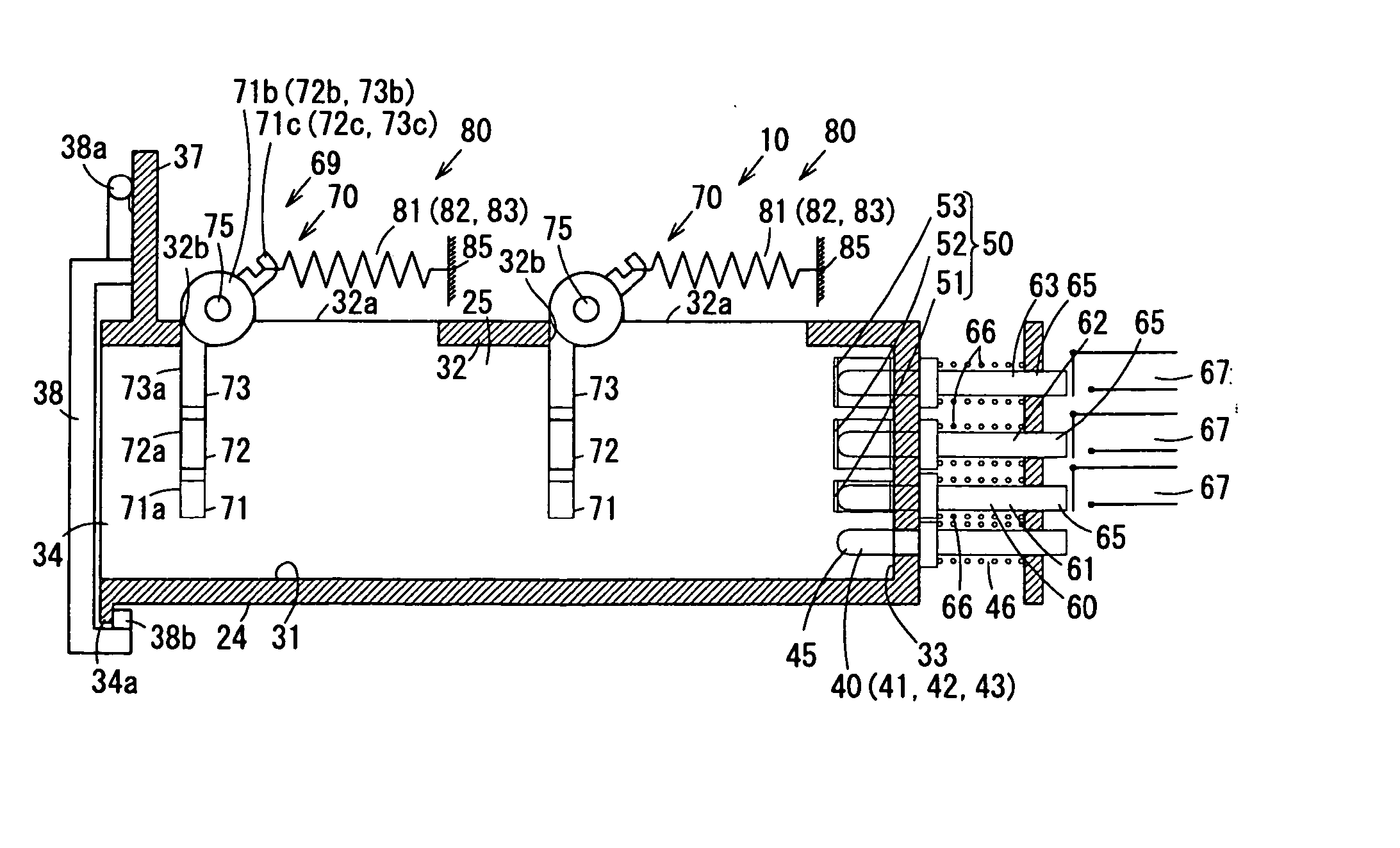
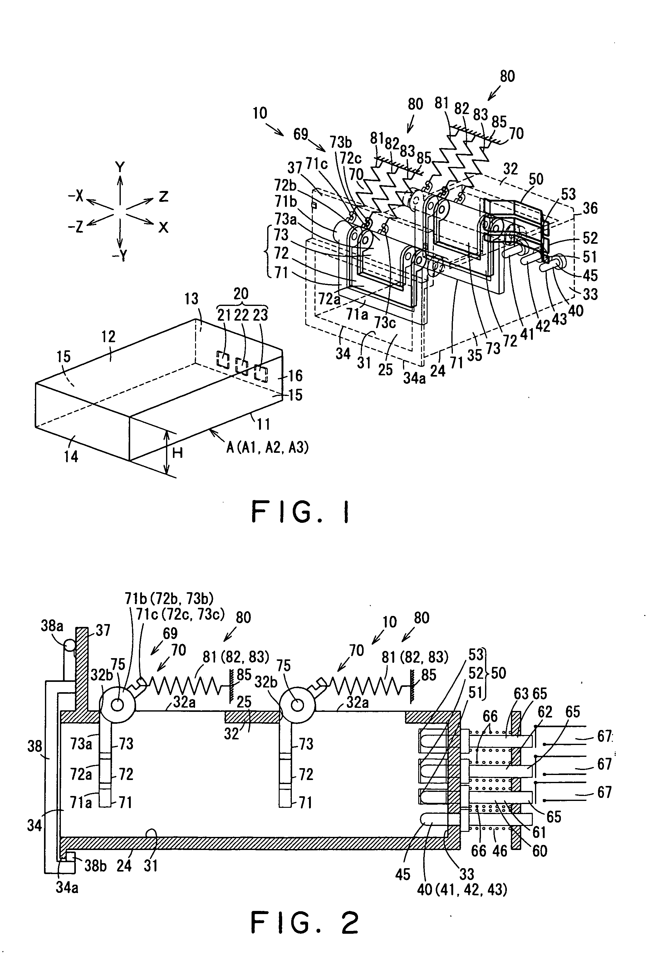
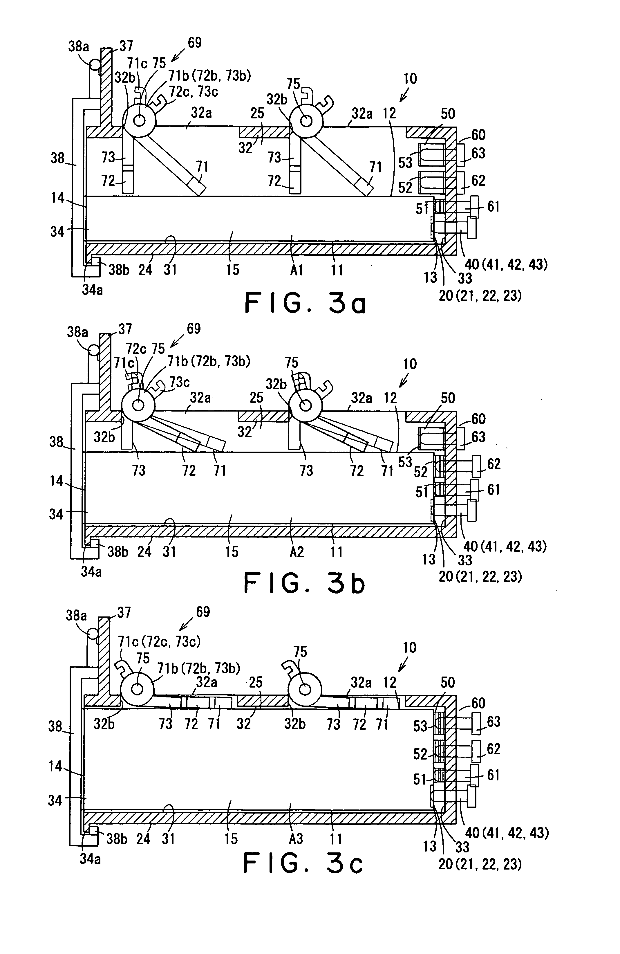
In each configuration of the embodiment described above, the third embodiment is constituted so that the pressing loads of regulating springs 81, 82 and 83 that urge movable-rotation first through third position regulating plates 71, 72 and 73 of the position regulating plate part 70 that abut opposing surface 12 of battery A can be adjusted. In other words, in the first and second embodiments described above, also in a case where the mass is changed due to a change in initial settings, friction coefficient accompanied by changes in limitations of durability performance and a change over time, or a change in specifications of battery A even when the shape is identical, as shown in the first embodiment, a mechanism can be secured in such a manner that battery A is pressed on the bottom surface part 31 of the storage compartment 25 so as to be positioned and held, and as shown in the second embodiment, battery A is ej...

fourth embodiment

Next, with reference to FIG. 10, the fourth embodiment is described.

In the fourth embodiment, concerning each of the above mentioned embodiments, the method of regulating positions and preventing falls out of batteries A1, A2 and A3 will be described wherein only an ejection urging part 50 is provided on end surface 33 at the back side of the storage compartment 25, while contact point part 40 and thickness judging part 60 that are other contact members exerting pressure forces are provided on surfaces other than end surface 33 at the back side of the storage compartment 25.

FIG. 10 is a perspective view where first battery A1 is loaded in storage compartment 25, wherein thickness judging part 60 is provided on a side surface part 35 on one side (X side) of the storage compartment 25 and contact point part 40 is provided on the other side (−X side). Although this storage compartment 25 is provided with, similar to those in other embodiments described above, a pair of position regul...


PUM


Abstract

The invention enables to load and unload batteries of Varying sizes efficiently. Storage apparatus 10 is equipped with storage compartment 25 capable of storing battery A of three different kinds of thicknesses and a lid that covers an insertion port 34 of the storage compartment 25. Storage compartment 25 is internally equipped with position regulating plate part 70 on ceiling part 32 and ejection urging part 50, a thickness judging part, and contact point part 40 on end surface 33 at the back side. Position regulating plate part 70 is equipped with three rotatable position regulating plates 71, 72 and 73. Position regulating plates 71, 72 and 73 are urged by regulating springs 81, 82 and 83 to protrude vertically into storage compartment 25. When battery A is inserted, one through three position regulating plates 71, 72 and 73 guide battery A to cause it to be pressed to bottom surface part 31 of the storage compartment 25. Any one of position regulating plates 71, 72 and 73 that does not abut battery A oppose perpendicularly to battery A prohibits movement of battery A in the thickness direction. By closing the lid, battery A can be loaded to be positioned in a prescribed position.

Description

FIELD OF THE INVENTION The invention relates to a storage apparatus for, for example, a battery compartment apparatus of a digital still camera, which is capable of storing multiple types of batteries. BACKGROUND OF THE INVENTION Conventionally, storage apparatuses have been known, which are mounted loadably and ejectably in a condition where box-shaped objects such as batteries and IC cards are stored. For example, the battery storage apparatus of Japanese Published Examined Utility Model Application No. 03-34048 is capable of storing two types of batteries, a lithium battery pack and an S-006P type battery, which is smaller than the lithium battery pack in external dimensions. The S-006P type battery, which is formed to fit the external shape of the lithium battery pack, is positioned to one side when it is inserted into the battery storage compartment by a side pressing member capable of elastically deforming and is pressed to be fixed by a top pressing member provided on a li...

Claims


Application Information

Patent Timeline
IPC IPC(8): H01M50/202H01M50/264
CPCH01M2/1027H01M2/1022Y02E60/10H01M50/267H01M50/264H01M50/202
Inventor ISHIKAWA, KAZUOKOBAYASHI, MASAO
Owner MONUMENT PEAK VENTURES LLC
Learn More