Intraocular lens

Inactive Publication Date: 2005-02-03
NIDEK CO LTD
View PDF2 Cites 51 Cited by
  • Summary
  • Abstract
  • Description
  • Claims
  • Application Information

AI Technical Summary

Problems solved by technology

However, this proposed intraocular lens is designed such that only an object located at a predetermined short (near) distance in front may be seen under magnification (i.e., such that an image of the object located at the predetermined short distance in front may be formed (focused) on a retina

Method used


Image

  • Intraocular lens
  • Intraocular lens
  • Intraocular lens

Examples


Embodiment Construction

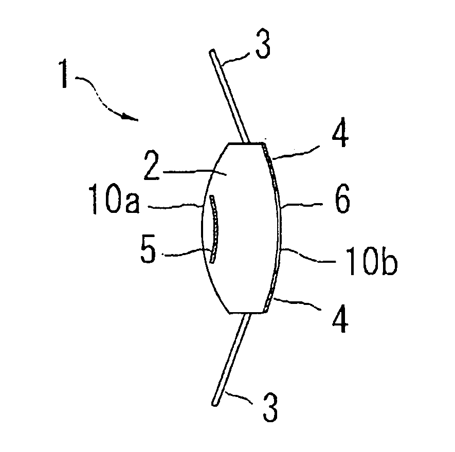
[0014] A detailed description of one preferred embodiment of an intraocular lens consistent with the present invention is provided below with reference to the accompanying drawings. FIG. 1 shows a schematic configuration of an intraocular lens for amblyopia consistent with the preferred embodiment of the present invention. Besides, a front side refers to a corneal side of the intraocular lens arranged inside an eye, and a rear side refers to a fundus side thereof. The intraocular lens 1 includes an optical part 2 which has predetermined refractive power, and supporting parts 3 which support and fix the optical part 2 within the eye. The intraocular lens 1 consistent with the preferred embodiment is a three-piece-type one which is prepared in such a manner that the optical part 2 and the supporting parts 3 are separately formed and then joined.

[0015] The optical part 2 is formed of a material which has been conventionally used for an optical part of an intraocular lens. For example,...


PUM


Abstract

An intraocular lens for amblyopia designed in consideration of normalizing vision as well as magnifying vision, is provided with an optical part having predetermined refractive power, which includes front and rear side refractive surfaces, a supporting part for supporting the optical part within the eye, a first reflecting part formed at a rear surface side of the optical part for reflecting an incident light bundle, which has passed through the front surface of the optical part, toward the front surface, and a second reflecting part formed at a front surface side of the optical part for reflecting the incident light bundle, which has been reflected by the first one, toward the rear surface, wherein the first and second reflecting parts form a reflecting telescopic system which forms a magnified image on a retina, and at least one of them has a property of transmitting a part of the light bundle.

Description

BACKGROUND OF THE INVENTION [0001] 1. Field of the Invention [0002] The present invention relates to an intraocular lens, more specifically relates to an intraocular lens for amblyopia. [0003] 2. Description of Related Art [0004] There is an intraocular lens for amblyopia provided with a telescopic (magnifying) function. As the intraocular lens, for example, such an intraocular lens is proposed that incorporates reflectors producing an effect of a folded telescope with a long focal length (refer to U.S. Pat. No. 4,759,761 corresponding to Japanese Patent Application Unexamined Publication No. Sho62-221345). [0005] However, this proposed intraocular lens is designed such that only an object located at a predetermined short (near) distance in front may be seen under magnification (i.e., such that an image of the object located at the predetermined short distance in front may be formed (focused) on a retina as a magnified image) without considering how to be seen with a normal phakic e...

Claims


Application Information

Patent Timeline
IPC IPC(8): A61F2/16
CPCA61F2/1648A61F2250/0053A61F2002/1683A61F2002/1651A61F2/1651
Inventor MURAKAMI, NAHONAKAHATA, YOSHIHIROSUNADA, TSUTOMU
Owner NIDEK CO LTD
Why Eureka
Try Eureka