
Storable sport trailer

a technology for sports equipment and storage trailers, which is applied in the direction of folding cycles, bicycles, and bicycles with multiple axes, etc., can solve the problems of difficult to place equipment on the roof of vehicles, difficult to remove equipment, and difficult to store equipment on vehicles. narrow width or profile, easy to store, easy to remove

Inactive Publication Date: 2005-02-10
YAKIMA PRODS
View PDF40 Cites 6 Cited by
  • Summary
  • Abstract
  • Description
  • Claims
  • Application Information

AI Technical Summary

Benefits of technology

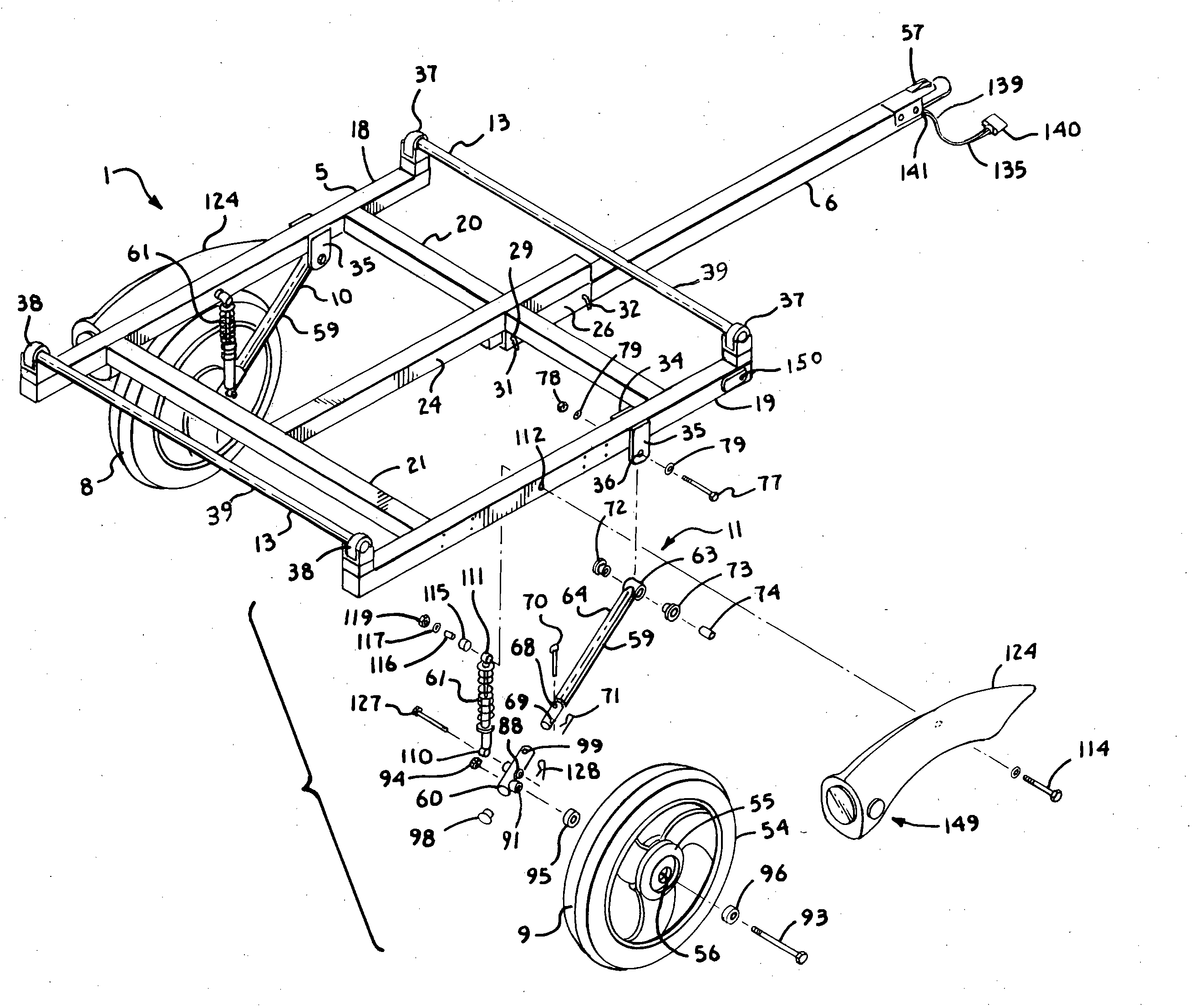
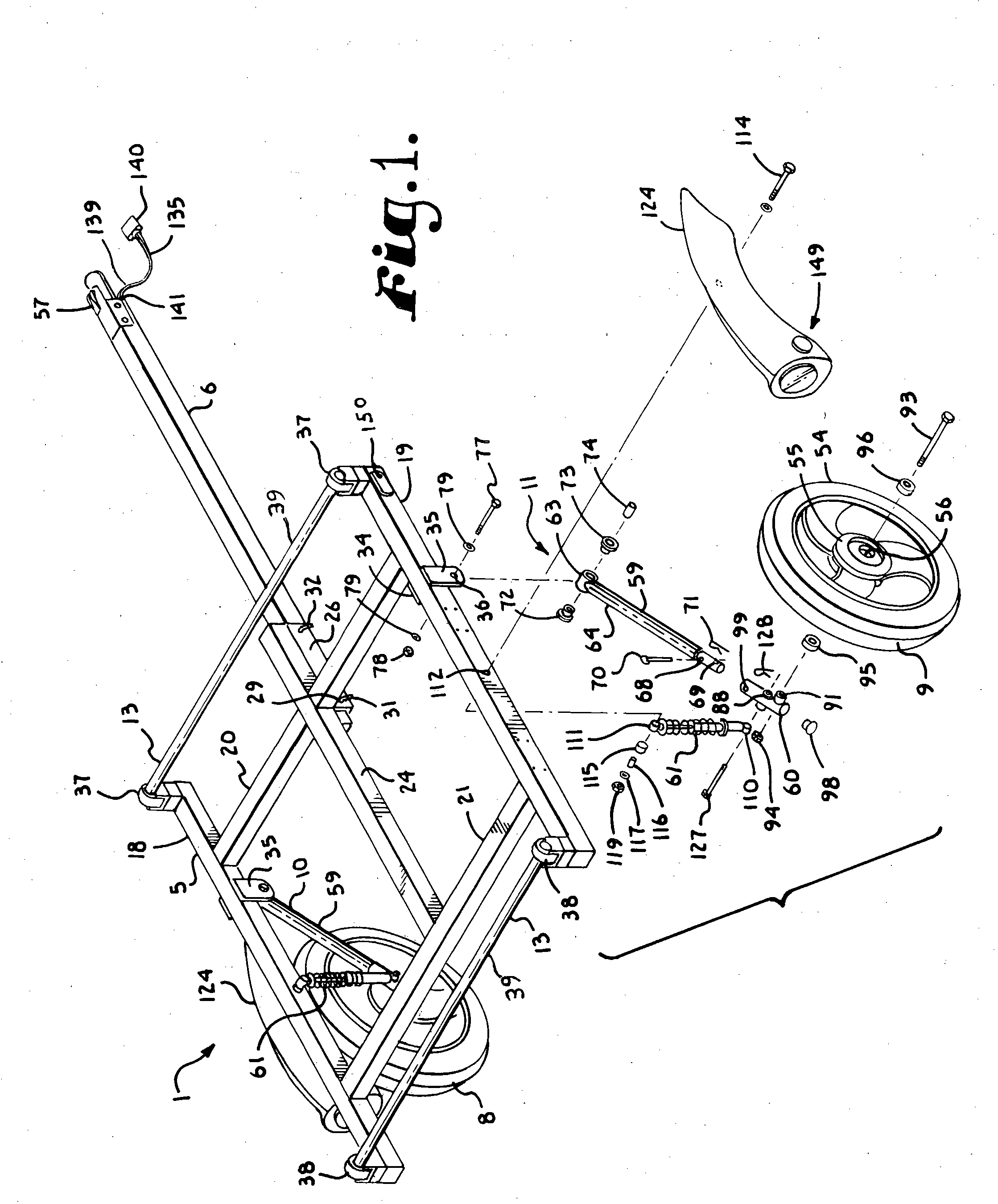
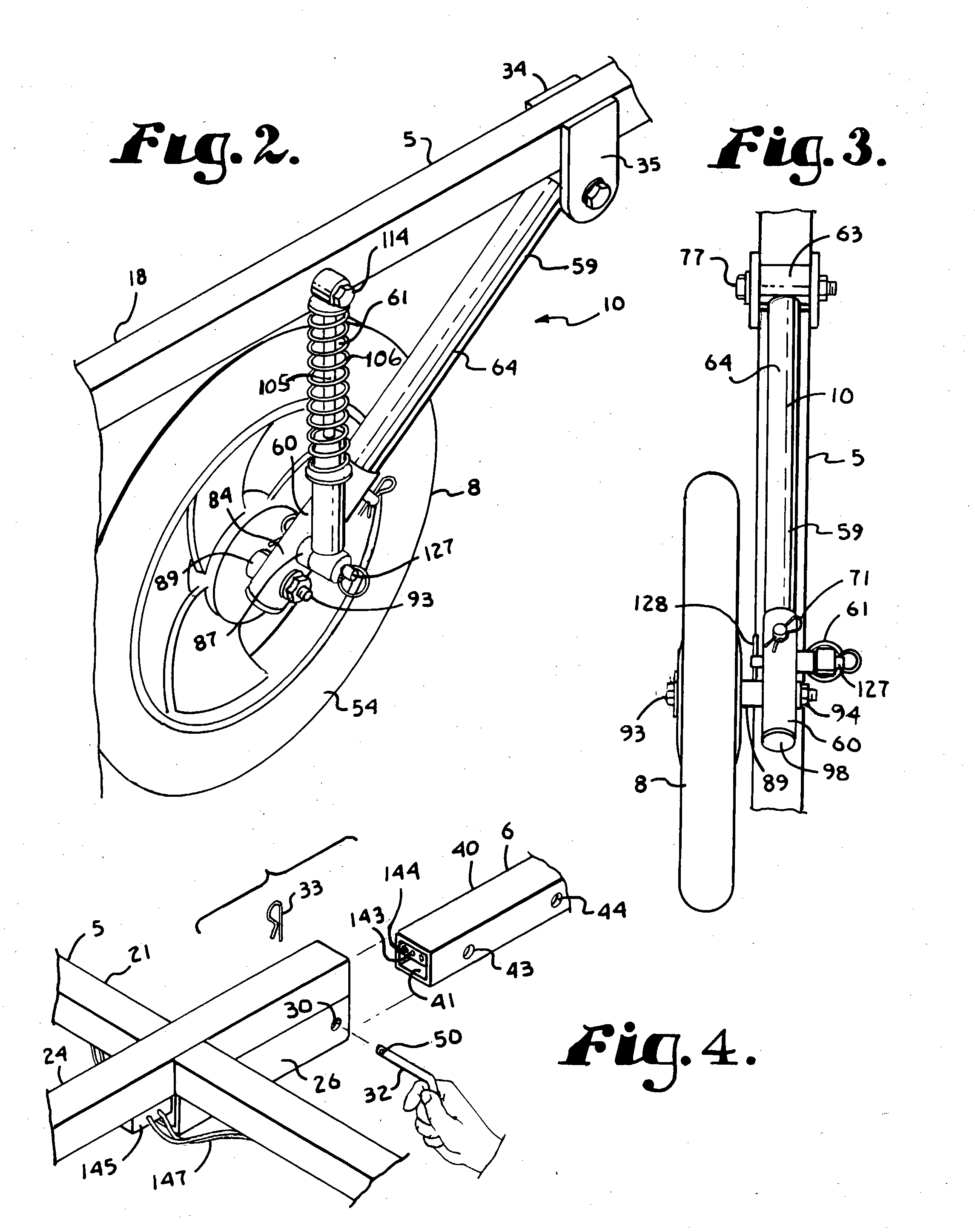
[0011] Therefore, the objects of the present invention are: to provide a utility trailer that is easily storable by leaning against a wall in a generally vertical alignment and, when so stored, has a relatively narrow width or profile, such that the trailer can be easily placed in a garage bay in the stored configuration with another vehicle; to provide such a trailer having wheels with wheel mounting assemblies or suspensions that each include a swing arm pivotally connected to a side rail of a frame of the trailer, a shock absorber pivotally connected to a respective side rail and a joining hub that is rotatably joined to a wheel and removably joined to the swing arm and shock absorber; to provide such a trailer wherein each swing arm is pivotally mounted beneath an associated side rail and each shock absorber is pivotally mounted to the side of an associated side rail, such that, when the swing arms and shock absorbers are disassembled from an associated hub, the swing arms and shock absorbers are free to rotate so as to be close and near parallel with a respective side rail, when the frame of the trailer is vertically aligned; to provide such a trailer wherein each swing arm is mounted on the underside of a respective side rail and an associated shock absorber is mounted to one side of the side rail, while a wheel is mounted on an opposite side of the side rail, when the trailer is in a use configuration; to provide such a trailer having a towing tongue that is removable for storage and that includes a wiring harness with a mounted receptacle that automatically mates with a fixed plug mounted on the trailer frame, when the tongue is joined the frame; to provide such a trailer wherein each hub with an associated wheel and the tongue are easily removed from or rejoined with the remainder of the trailer by removing or replacing manual pins without requiring tools; to provide such a trailer that can be easily modified to adjust for heavier or lighter loads by changing shock absorbers; and to provide such a trailer that is relatively inexpensive to produce, easy to use and especially well adapted for the intended usage thereof.
[0012] Other objects and advantages of this invention will become apparent from the following description taken in conjunction with the accompanying drawings wherein are set forth, by way of illustration and example, certain embodiments of this invention.
[0013] The drawings constitute a part of this specification and include exemplary embodiments of the present invention and illustrate various objects and features thereof.

Problems solved by technology

Many of these activities require equipment that will not fit in many transporting vehicles or may cause damage if put in such a vehicle.
A standard rack can be obtained for transporting certain of these items on top of a transporting vehicle, but it is difficult to place the equipment on the roof of the vehicle.
For example, a bicycle is very ungainly and relatively heavy that can be loaded on a vehicle's roof, but only with great difficulty, especially if only one person is available.
However, the trailer, when in a use configuration, will take up an entire garage bay that may be needed for other purposes, such as garaging the family car.
In such instances, removal or replacement of the tongue requires a substantial amount of handling of wiring.

Method used


Image

  • Storable sport trailer
  • Storable sport trailer
  • Storable sport trailer

Examples


Embodiment Construction

[0023] As required, detailed embodiments of the present invention are disclosed herein; however, it is to be understood that the disclosed embodiments are merely exemplary of the invention, which may be embodied in various forms. Therefore, specific structural and functional details disclosed herein are not to be interpreted as limiting, but merely as a basis for the claims and as a representative basis for teaching one skilled in the art to variously employ the present invention in virtually any appropriately detailed structure.

[0024] The reference numeral 1 generally illustrates a trailer in accordance with the present invention having a load supporting frame 5, a removable tongue 6, a pair of wheels 8 and 9, a pair of wheel mounting assemblies 10 and 11 and a load support system 13.

[0025] The frame 5 includes a pair of front to rear extending and laterally spaced side rails 18 and 19 that are fixably joined together by a front rail 20 and a rear rail 21 to form a generally rigi...


PUM


Abstract

A utility trailer having a low profile storage configuration. The trailer includes a frame, wheels, mounting assemblies for the wheels, a removable tongue and a wiring system. Each mounting assembly includes a swing arm and a shock absorber that are joined by a hub that is easily removable and in turn is rotatably joined to a wheel. Each swing arm is pivotally joined to an underside of a side rail of the frame. Each shock absorber is pivotally attached to an inner side of the side rail and each wheel is positioned outwardly of a respective side rail opposite a respective shock absorber. The wiring system includes a harness located in the interior of the tongue. The wiring system also includes a plug mounted on the frame and a receptacle mounted on the tongue that automatically mate when the tongue is joined to the frame.

Description

BACKGROUND OF THE INVENTION [0001] The present invention is a utility trailer for hauling sports equipment and the like that is easily convertible to a low profile configuration for storage against a wall in a garage bay with a car or other vehicle. [0002] Various types of outdoor sporting activities are becoming increasingly popular. Many of these activities require equipment that will not fit in many transporting vehicles or may cause damage if put in such a vehicle. Such equipment includes items such as motorized bikes, powered watercraft, bicycles, kayaks and the like. A standard rack can be obtained for transporting certain of these items on top of a transporting vehicle, but it is difficult to place the equipment on the roof of the vehicle. For example, a bicycle is very ungainly and relatively heavy that can be loaded on a vehicle's roof, but only with great difficulty, especially if only one person is available. Other equipment is just to heavy or large to place on a roof. [...

Claims


Application Information

Patent Timeline
Patent Type & Authority Applications(United States)
IPC IPC(8): B62D63/06
CPCB62D63/061
Inventor KOCH, JOHN
Owner YAKIMA PRODS
Learn More