
Apparatus and method for intelligent call routing and call return

a call routing and call return technology, applied in the field of telecommunications, can solve the problems of not providing intelligent call routing capabilities for routing service calls to predetermined service or control centers, and prior attempts to provide system flexibility in terms of providing various routing and/or call return

Inactive Publication Date: 2005-02-10
AT&T LABS
View PDF72 Cites 8 Cited by
  • Summary
  • Abstract
  • Description
  • Claims
  • Application Information

AI Technical Summary

Benefits of technology

"The present invention provides intelligent call routing and call return features in an advanced intelligent network (AIN) or AIN-type network environment. The invention allows for intelligent call routing based on the location of the calling party and various routing options, such as the NPA-NXX of the calling number or the time-of-day. The invention also allows for automatic routing of calls to an appropriate service or control center based on the location of the calling party and the availability of designated service or control centers. The invention can provide flexibility in terms of providing various routing and call return options that may be combined. The invention can also automatically direct or route service calls to an appropriate service network location based on the location of the calling party and one or more routing options. The invention can be used in an AIN or AIN-type network environment and can be implemented in a signaling communication system. Overall, the invention provides advanced call routing capabilities for service calls in an AIN or AIN-type network environment."

Problems solved by technology

While prior AIN or AIN-type intelligent network applications have provided various call forwarding and routing features as indicated above, such prior attempts have not provided intelligent call routing capabilities for routing service calls to predetermined service or control centers.
Prior attempts have also not provided system flexibility in terms of providing various routing and / or call return options that may be combined with routing based on the location of the calling party.

Method used


Image

  • Apparatus and method for intelligent call routing and call return
  • Apparatus and method for intelligent call routing and call return
  • Apparatus and method for intelligent call routing and call return

Examples


Embodiment Construction

[0085] Referring to the accompanying drawings, a detailed description of the preferred embodiments, features and aspects of the present invention will be provided.

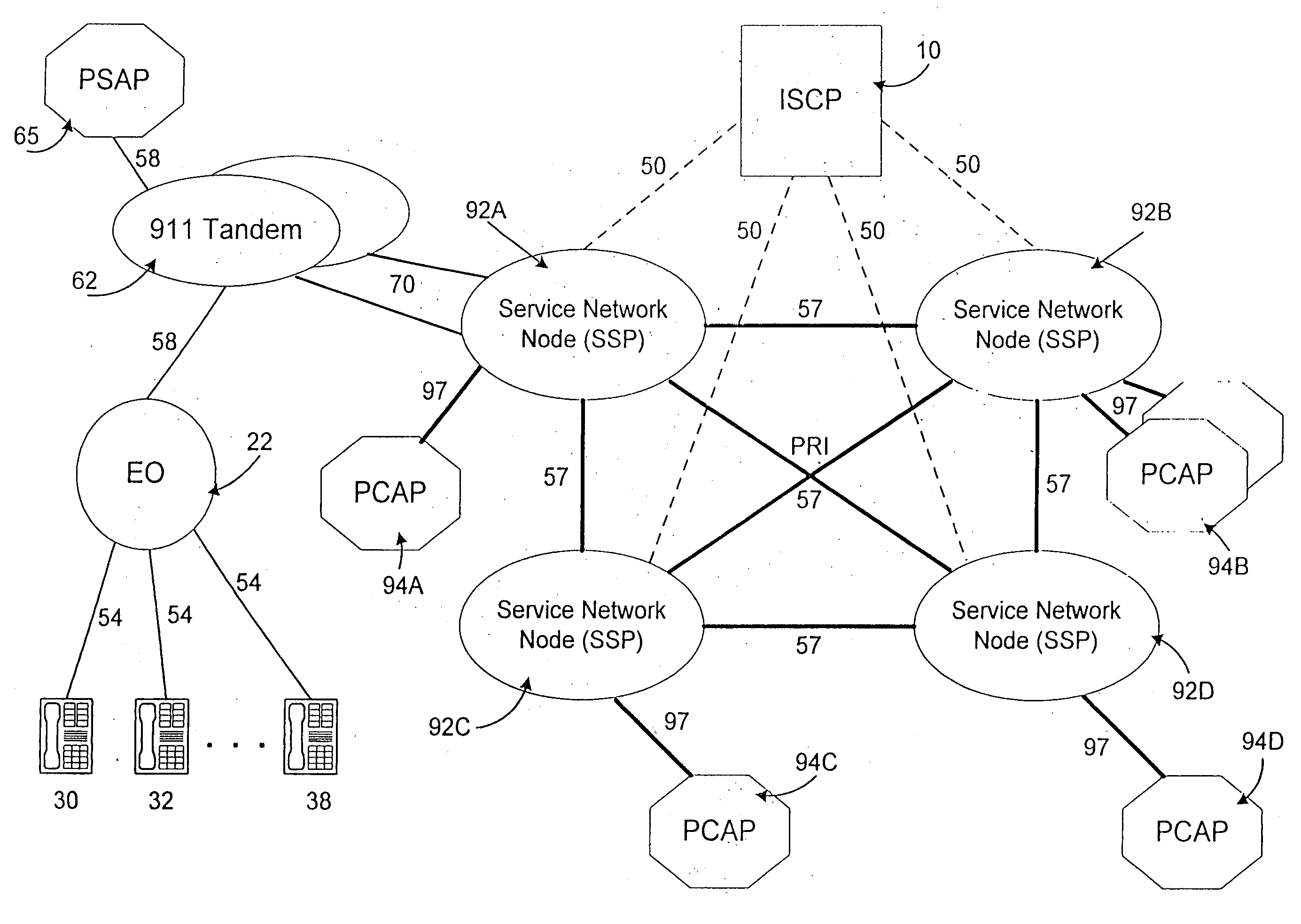
[0086] The present invention relates to an apparatus and method for providing intelligent call routing and call return capabilities in a telecommunications network environment. The intelligent call routing features of the present invention may be utilized for routing service calls to an appropriate service or control center, in accordance with one or more routing options. The routing features of the present invention may also be combined with the call return capabilities, for returning the service call over the network to an appropriate location. By way of a non-limiting example, the present invention may be utilized for routing public service calls, such as emergency or poison assistance calls, to one of a plurality of service or control centers depending upon the location of the calling party (i.e., the poisoned party)....


PUM


Abstract

A computer program for routing a service call from a calling party to a service network having a plurality of service network locations, the program stored in a computer-readable medium. The program includes receiving a service call request to connect the calling party to one of the service network locations, determining a location of the calling party by searching a Number Plan Area (NPA) table to determine an NPA of the calling number of the calling party, identifying one of the service network locations for receiving the service call request, and identifying routing information for routing the service call request to the receiving service network location, and completing the service call request to the receiving service network location.

Description

[0001] This is a continuation of U.S. patent application Ser. No. 09 / 645,325, filed Aug. 25, 2000, which is a continuation of U.S. patent application Ser. No. 09 / 480,461, filed Jan. 11, 2000, (now U.S. Pat. No. 6,185,282, issued Feb. 6, 2001) which is a continuation of U.S. patent application Ser. No. 08 / 829,235, filed Mar. 31, 1997, (now U.S. Pat. No. 6,075,853, issued Jun. 13, 2000), the contents of which are expressly incorporated by reference herein in its entirety.BACKGROUND OF THE INVENTION [0002] 1. Field of the Invention [0003] The present invention generally relates to the field of telecommunications. More particularly, the present invention relates to a telecommunications network environment having intelligent call routing and call return capabilities for routing service calls, such as emergency or poison assistance calls, to an appropriate service or control center. [0004] 2. Acronyms [0005] The written description provided herein contains acronyms, which refer to various...

Claims


Application Information

Patent Timeline
Patent Type & Authority Applications(United States)
IPC IPC(8): H04Q3/00
CPCH04Q3/0029
Inventor BOECKMAN, MICHAEL W.PLUNKETT, WILLIAM E.
Owner AT&T LABS
Learn More