
Cochlear ear implant

a cochlear implant and ear technology, applied in the field of transcanal and transtympanic cochlear implant devices, can solve the problems of profound hearing loss, inability to generate electrical energy and transmit to the brain, and inability to use a hearing aid to process sound

Inactive Publication Date: 2005-02-10
SACHA MIKE K
View PDF30 Cites 46 Cited by
  • Summary
  • Abstract
  • Description
  • Claims
  • Application Information

AI Technical Summary

Benefits of technology

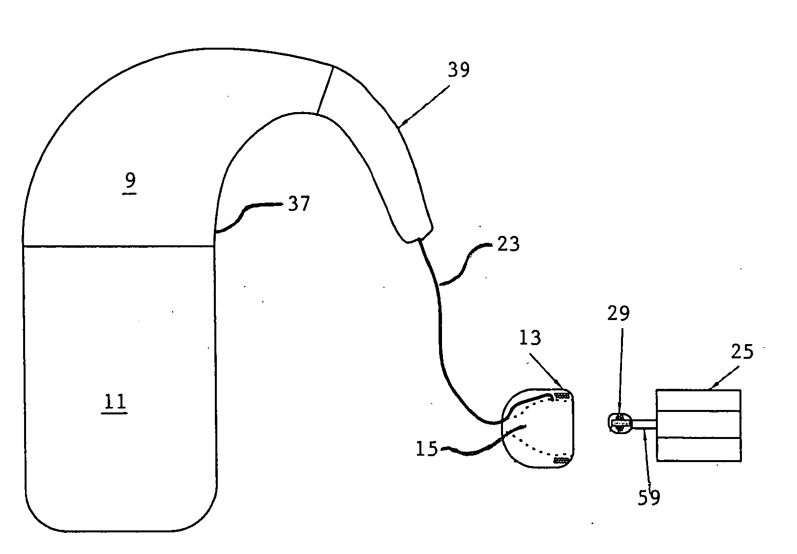
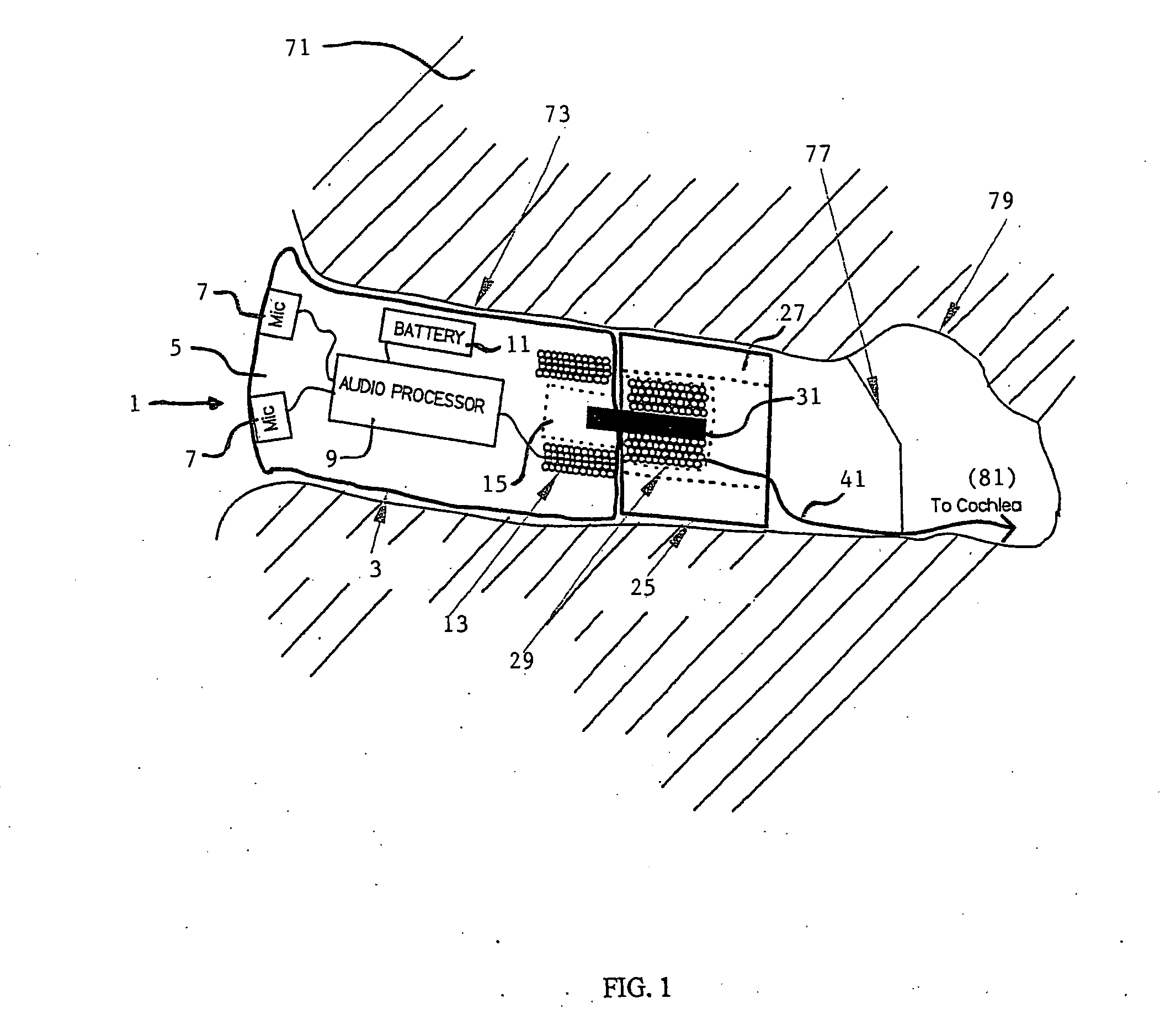
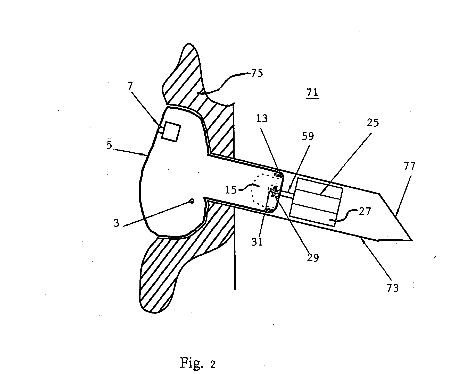
[0013] The present invention addresses the aforementioned disadvantages by providing an improved cochlear implant that does not require significant surgery under general anesthesia, that does not destroy residual hearing, and is small enough to fit within a person's ear canal. The cochlear implant of the present invention includes an exterior ear module, an interior ear module, and an implanted electrode array. The exterior ear module is preferably located in the exterior region of the ear canal, though in alternative embodiments, the exterior ear module may also be located behind the ear. The interior ear module is located in the ear canal immediately exterior to the tympanic membrane. Finally, the wire electrode extends from the interior ear module through the tympanic membrane so that the electrode distal extremity engages the cochlear nerves. The most exterior module, referred to as the exterior ear module, is removable, and communicates audio signals to the semi-permanent interior ear module, which in turn, transmits electrical stimulus signals to the electrode array.

Problems solved by technology

Unfortunately, the use of a hearing aid does not enable such an ear to process sound.
Unfortunately, some people suffer damage or depletion of the hair cells resulting in profound hearing loss.
In these cases, electrical energy cannot be generated and transmitted to the brain.
Without these electrical impulses, the hearing nerves cannot carry messages from the cochlea to the brain and even the loudest of sounds cannot be heard.
Although the hair cells in the cochlea may be damaged, there are usually some surviving hearing nerves.
Unfortunately, cochlear implants suffer from significant drawbacks.
The main problem with conventional cochlear implants is that during the implantation phase, residual hearing can be destroyed.
Since the length of typical electrode arrays extend beyond the first cochlear bend, it is forced into the curvature by deflecting off the cochlear wall, causing damage to the Stria Vascularus, Spiral Ligament, and even the Basilar Membrane regions.
This damage, potentially, precludes these patients from utilizing future technological developments in hearing science.
Another problem is that traditional cochlear implants require temporal bone excavation, within which the implanted electronics module is placed and through which the electrode array is presented-to the cochlea.
This operation requires the patient to be placed under general anesthesia which represents an additional risk.
Another problem with traditional cochlear implants is their complexity.
This requires the inductive link to transfer power as well as audio information, simultaneously, to the implanted module, thus increasing the complexity of the overall system.
Cochlear implants are also very expensive, requiring surgery, anesthesia, hospital stay, and cochlear programming as each cochlear implant must also be programmed individually for each user which is also expensive and time consuming.
The entire procedure is prohibitively expensive and impractical for the vast majority of deaf people in the world.
Moreover, few doctors in developing countries have the sophistication, expertise and equipment to perform a facial recess mastoidectomy.

Method used


Image

  • Cochlear ear implant
  • Cochlear ear implant
  • Cochlear ear implant

Examples


Embodiment Construction

[0049] While the present invention is susceptible to the embodiment in various forms, as shown in the drawings, hereinafter will be described the presently preferred embodiments of the invention with the understanding that the present disclosure is to be considered as a exemplification of the invention and is not intended to limit the invention to the specific embodiments illustrated.

[0050] With reference to the figures, the cochlear ear implant 1 of the present invention includes three primary components, namely an exterior ear module 3, an interior ear module 25 and an electrode assembly 41. The exterior module may be constructed in various forms depending on the construction of the patient's ear. For example, for the preferred embodiment of the cochlear ear implant shown in FIG. 1, the exterior ear module 3 is located in the exterior region of the auditory canal 73. The exterior ear module is made in the same manner as a conventional in-the-ear hearing aid. First, an impression ...


PUM


Abstract

A simple cochlear implant is provided that can be implanted in a doctor's office under local anesthesia, which does not destroy residual hearing, and in a preferred embodiment, which is small enough to fit within a person's ear canal. The cochlear ear implant includes an exterior ear module, an interior ear module, and a cochlear electrode array. The exterior ear module includes a hollow housing within which are located the active electrical components including a microphone, power supply, and processor. The exterior ear module is easily removable from the body without surgery and is positioned in the auditory canal, the concha bowl or behind the pinna. The interior ear module is a semi-permanent assembly located immediately exterior to the tympanic membrane. It is a simple passive module for relaying signals to the electrode array. The communication of auditory signals from the exterior ear module to the interior ear module may be achieved by various techniques including by direct electrical transmission. However, the communication between the exterior and interior ear modules is preferably accomplished using a transcanal induction link. The electrode array extends from the interior ear module through the tympanic membrane to engage the cochlea. The electrode array includes an implanted active electrode, a return electrode, and a biocompatible miniature connector for connecting to the interior ear module.

Description

RELATED APPLICATIONS [0001] This application is a continuation-in-part of my co-pending U.S. Provisional Application Ser. No. 60 / 492,347, filed Aug. 4, 2003.BACKGROUND OF THE INVENTION [0002] The present invention relates to a transcanal, transtympanic cochlear implant device ideally suited for those profoundly deaf, where conventional hearing aids are of limited or no value. A profoundly deaf ear is typically one in which the sensory receptors of the inner ear, called hair cells, are damaged or diminished. Unfortunately, the use of a hearing aid does not enable such an ear to process sound. Meanwhile, cochlear implants bypass damaged hair cells and directly stimulate the hearing nerves with an electrical current, allowing individuals who are profoundly or totally deaf to hear. [0003] The ear is an amazing structure consisting of three main parts including the outer ear, the middle ear and the inner ear. The outer ear includes the visible outer portion of the ear called the auricle ...

Claims


Application Information

Patent Timeline
IPC IPC(8): A61N1/05A61N1/36
CPCA61N1/0541A61N1/37223A61N1/36032A61N1/36036A61N1/36038
Inventor SACHA, MIKE K.
Owner SACHA MIKE K
Learn More