
Digital broadcasting receiver and digital broadcasting receiving method

Inactive Publication Date: 2005-02-10
KK TOSHIBA
View PDF8 Cites 46 Cited by
  • Summary
  • Abstract
  • Description
  • Claims
  • Application Information

AI Technical Summary

Benefits of technology

An aspect of the present invention is to provide a digital broadcasting receiver and a receiving method in which a service list can be acquired from an area having an advantageous receiving state of the receiver, and receiving environments can be set. Moreover, there are provided a digital broadcasting receiver and a receiving method in which a service list is easily acquired without imposing any burden to a user, even when an installation area of the receiver is changed or the receiver is moved.

Problems solved by technology

However, when actual broadcasting companies are considered, the radio waves from the station of the broadcasting company of each broadcasting area are not necessarily separated exactly for each broadcasting area.
In this case, if the audience residential area is first set in the digital broadcasting receiver, it may fail to set the channel from the adjacent area having good receiving conditions.
(C) Furthermore, in view of the increase in broadcasting companies that is likely to occur, the user may need to reset the receiver, thus causing an inconvenience to the user.

Method used


Image

  • Digital broadcasting receiver and digital broadcasting receiving method
  • Digital broadcasting receiver and digital broadcasting receiving method
  • Digital broadcasting receiver and digital broadcasting receiving method

Examples


Embodiment Construction

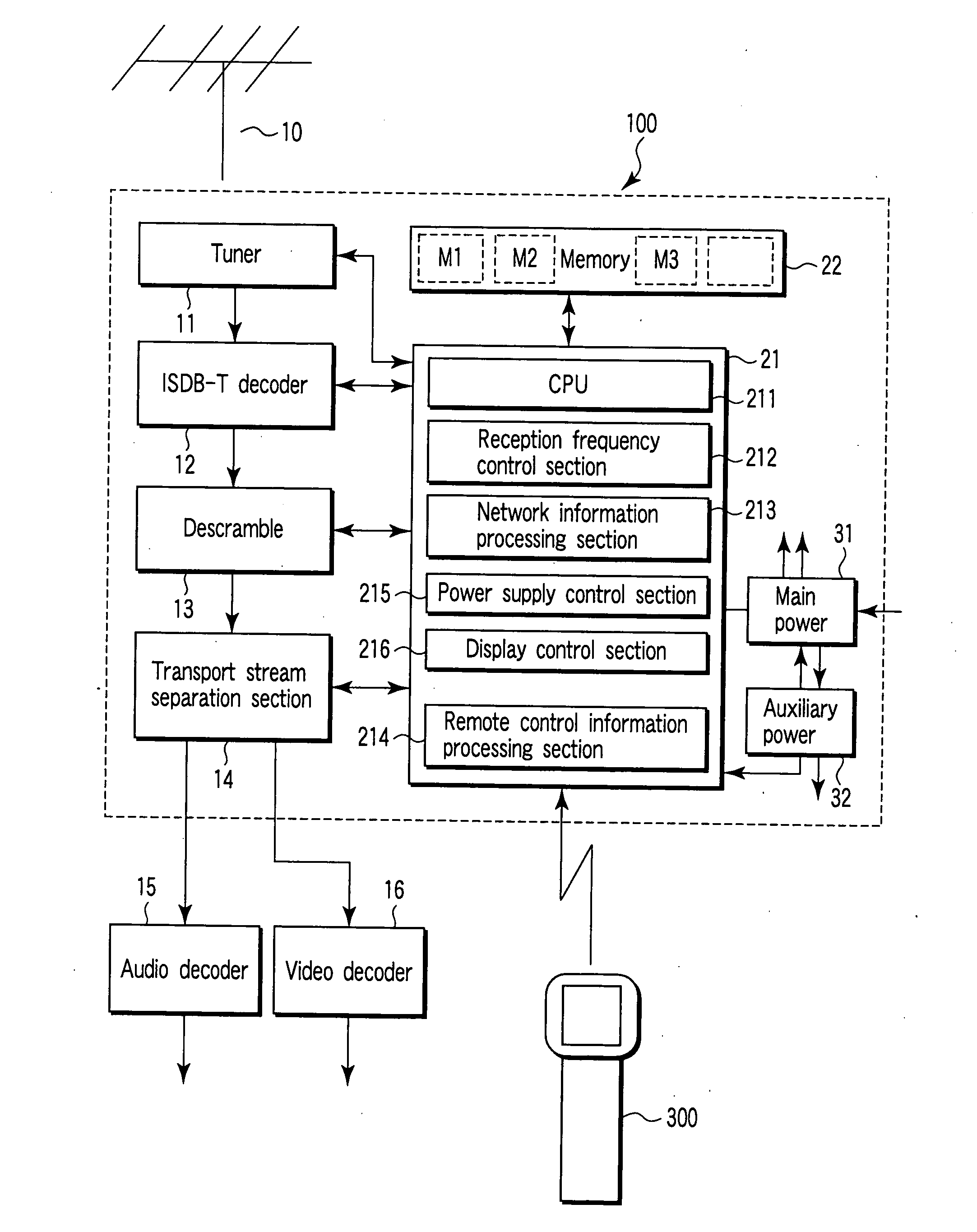
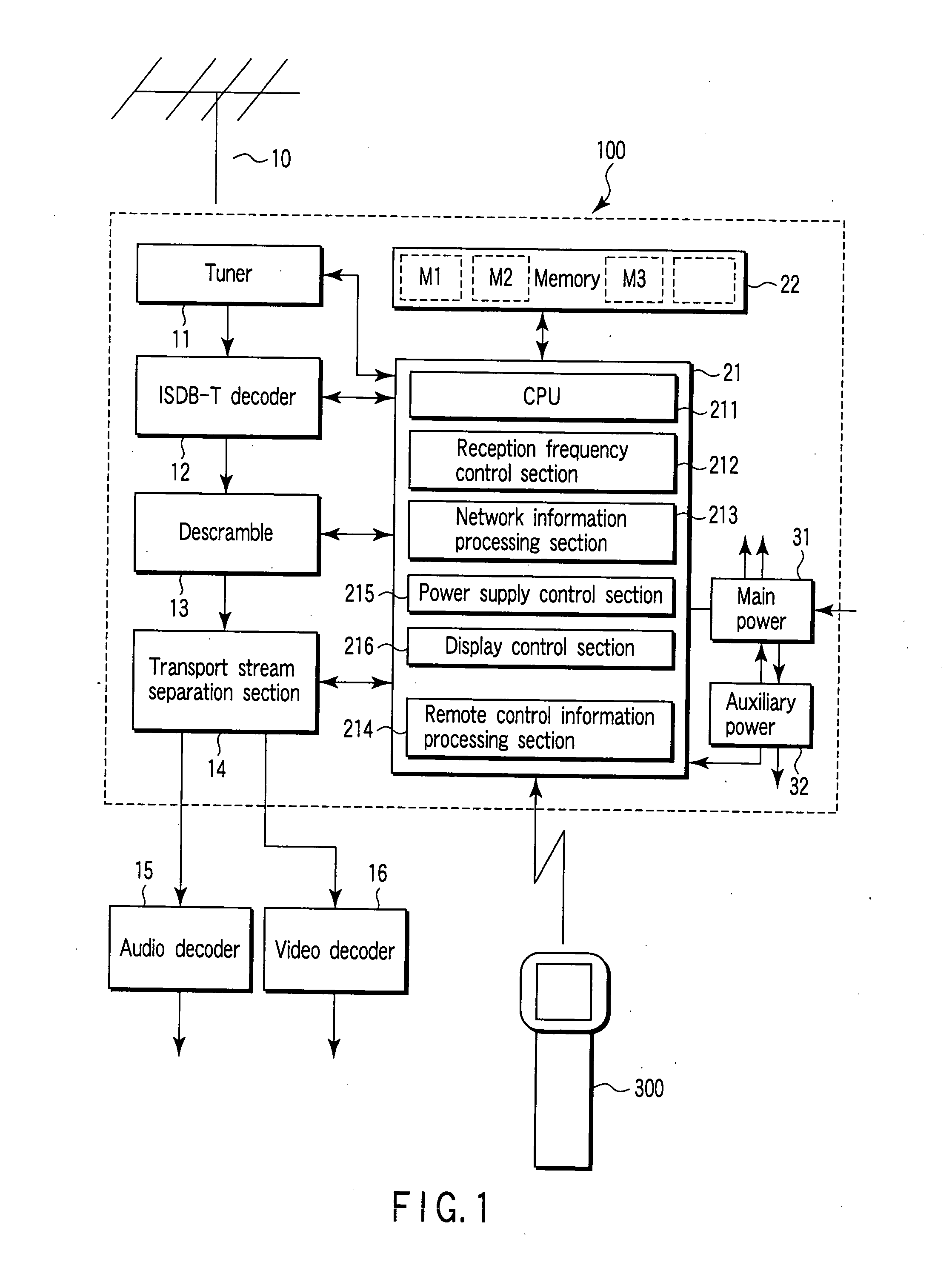
An embodiment of the present invention will be described hereinafter with reference to the drawings. FIG. 1 is a diagram showing a constitution of a main part of the present invention.

A digital broadcasting receiver 100 is connected to a UHF antenna 10 via a cable. Radio waves received by the UHF antenna 10 are guided to a tuner 11. A channel selection operation of the tuner 11 is controlled by a system control section 21.

An intermediate frequency signal obtained by the channel selection operation of the tuner 11 is input into an integrated services digital broadcasting-terrestrial (ISDB-T) decoder 12, and decoded into a stream signal. The stream signal is descrambled by a descrambler 13, and converted to an original transport stream. The transport stream is input into a transport stream separation section 14.

The transport stream separation section 14 separates packets which are, respectively, including control information, video information, audio information, digital servic...


PUM


Abstract

A tuner varies a reception frequency to receive each channel. A transport stream (TS) separation section, and a system control section separates network information table (NIT) information from the TS of each channel. A memory stores network identification (N_id) information which is included in the NIT and which can be identified for each residential area. The residential area to which most (N_id) information belongs is specified from a plurality of pieces of (N_id) information stored in the memory, and it is assumed that a receiver is installed in the area.

Description

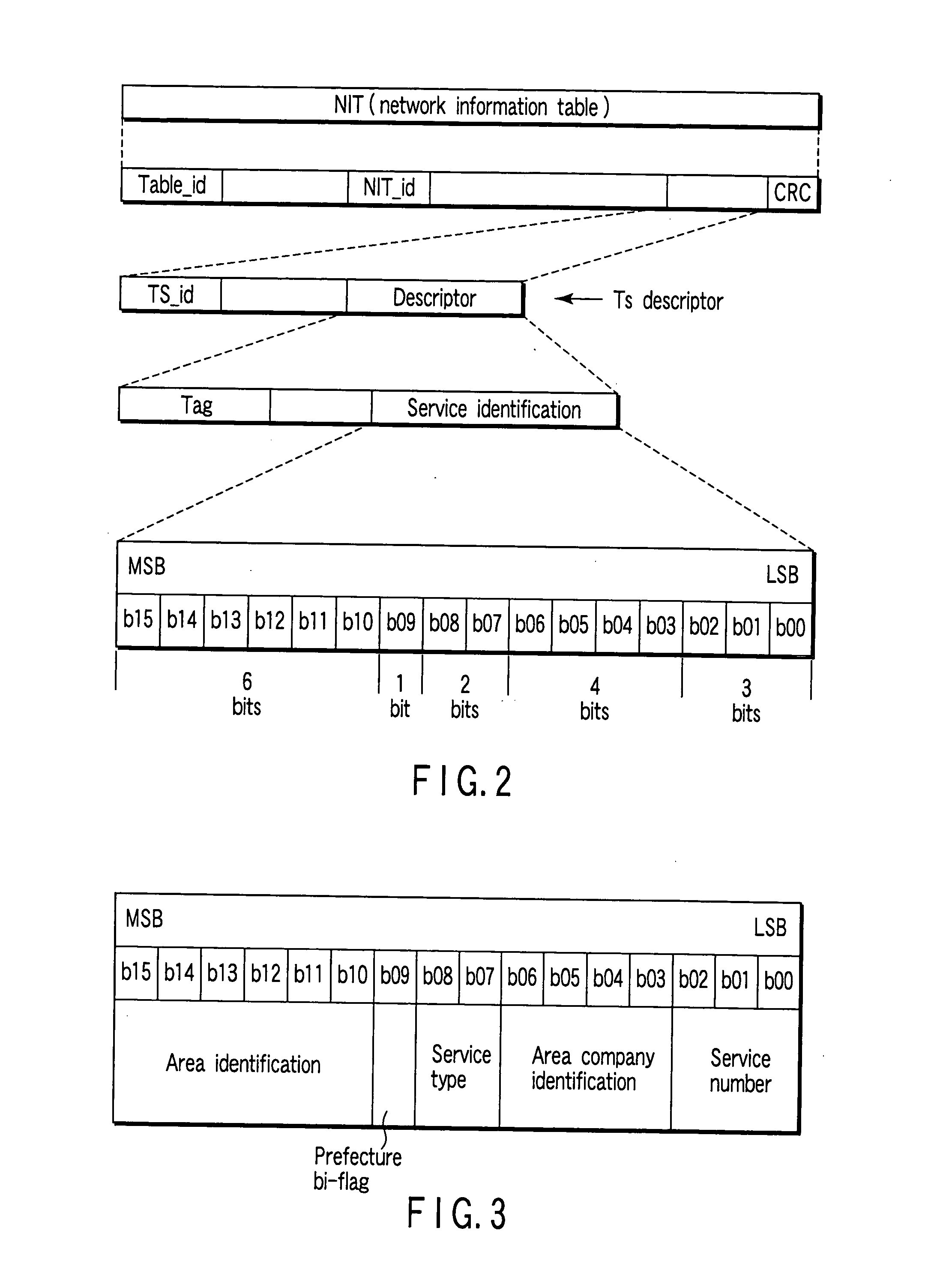
CROSS-REFERENCE TO RELATED APPLICATIONS This application is based upon and claims the benefit of priority from prior Japanese Patent Application No. 2003-290452, filed Aug. 8, 2003, the entire contents of which are incorporated herein by reference. BACKGROUND OF THE INVENTION 1. Field of the Invention The present invention relates to a digital broadcasting receiver and a digital broadcasting receiving method in which a method of acquiring a service list is improved, and is useful as a device for receiving terrestrial digital broadcasting. 2. Description of the Related Art In terrestrial digital broadcasting which has been developed in recent years, a packet including a network information table (hereinafter referred to as NIT) is included in a transport stream (hereinafter referred to as TS). The NIT includes various types of information necessary for receiving a program. The NIT includes a remote controller key id. The remote controller key id is used to allocate a key number ...

Claims


Application Information

Patent Timeline
IPC IPC(8): H04B1/16H04H20/00H04H60/50H04H60/73H04N5/00H04N5/445H04N7/025H04N7/03H04N7/035H04N7/20
CPCH04H60/50H04H60/73H04N21/235H04N21/4524H04N21/435H04N21/443H04N21/4345
Inventor HATANAKA, SHINICHI
Owner KK TOSHIBA
Learn More