Television receiver integrated with recording and reproducing device

a technology of television receiver and recording and reproducing device, which is applied in the field of television receiver, can solve the problems of y/c signal becoming idle, composite signal cannot be converted into y/c signal,

Inactive Publication Date: 2010-12-28
FUNAI ELECTRIC CO LTD
View PDF16 Cites 0 Cited by
  • Summary
  • Abstract
  • Description
  • Claims
  • Application Information

AI Technical Summary

Benefits of technology

[0009]The present invention has been finalized in view of the drawbacks, and an object of the present invention is that it provides a television receiver integrated with a recording and reproducing device, which is capable of displaying clear broadcast pictures on a monitor and further displaying broadcast picture without being affected by a converting circuit of a video signal.
[0011]As described above, when the receiving state of broadcast signal is good, the broadcast pictures are displayed on the monitor by using the Y / C signal or the component signal. Therefore, without any problems occurring when the broadcast pictures are displayed by a composite signal (for example, dot disturbance caused by a color signal which still remains in a luminance signal or cross-color caused when a color signal and a luminance signal are mixed with each other), clear television broadcast pictures can be displayed on the monitor. Furthermore, since the encoder used for producing the Y / C signal or the component signal is originally a device which records and reproduces a broadcast signal, the cost for an additional device is not needed. In the meantime, when the receiving state of broadcast signal is not good, the broadcast pictures are displayed on the monitor by the composite signal to be output from the receiver. Therefore, even when the Y / C signal or the component signal cannot be produced from the composite signal by the video decoder and the video encoder, a user can watch broadcast picture corresponding to the receiving state of the broadcast signal.
[0012]In the embodiment of the present invention, the recording medium is a DVD, and broadcast pictures and reproduced pictures are displayed by using the Y / C signal between the Y / C signal and component signal. Therefore, a circuit for producing the component signal is not needed, and thus the cost of the device can be reduced.

Problems solved by technology

In this case, however, when a receiving state of the broadcast signal is bad and a signal level of the composite signal is low, the composite signal cannot be converted into the Y / C signal due to the limited capacity of the circuit for recording and reproducing.
Therefore, in that case, there occurs a problem in that the Y / C signal becomes in an idle state and thus the broadcast pictures are not displayed on a monitor.

Method used


Image

  • Television receiver integrated with recording and reproducing device
  • Television receiver integrated with recording and reproducing device
  • Television receiver integrated with recording and reproducing device

Examples


Embodiment Construction

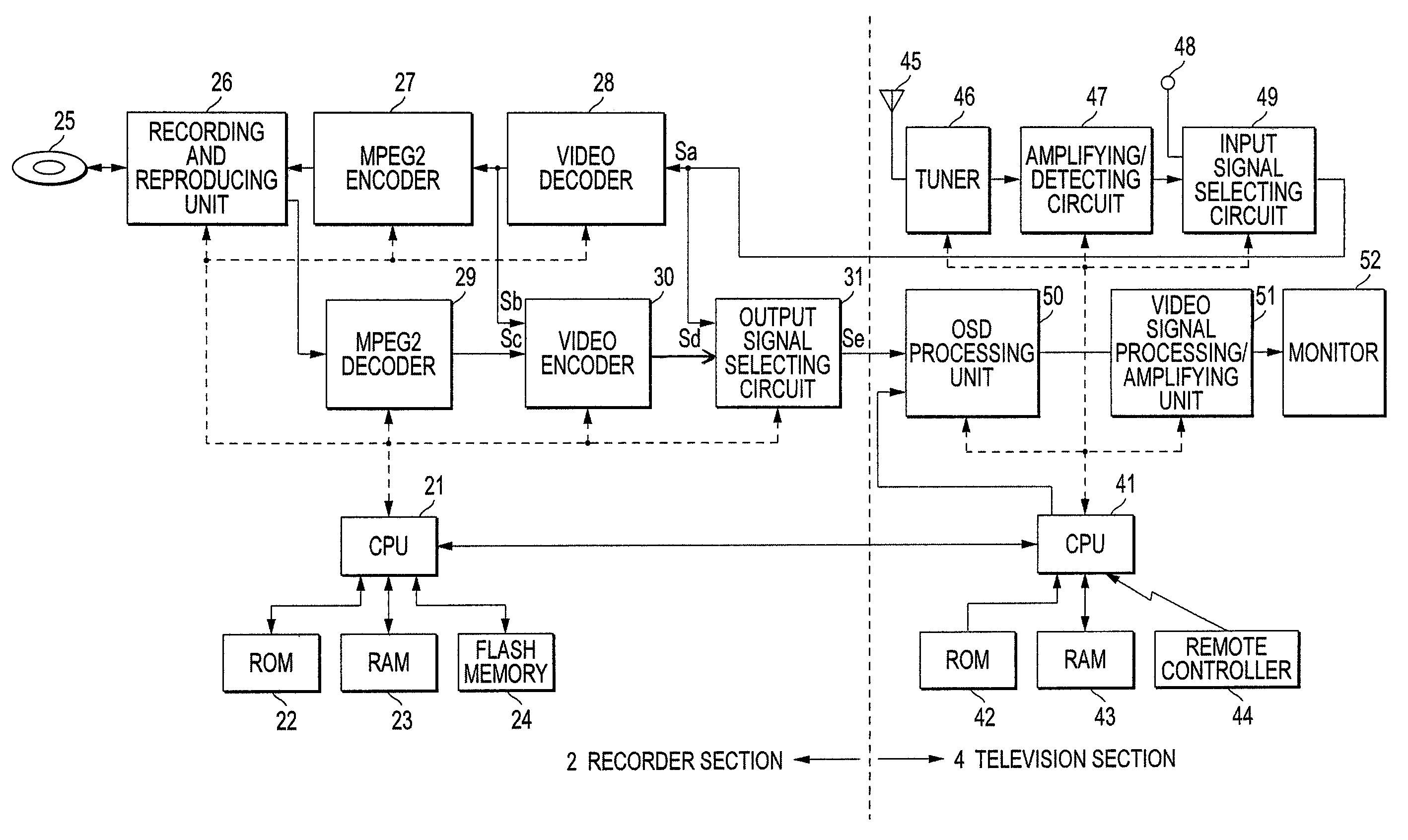
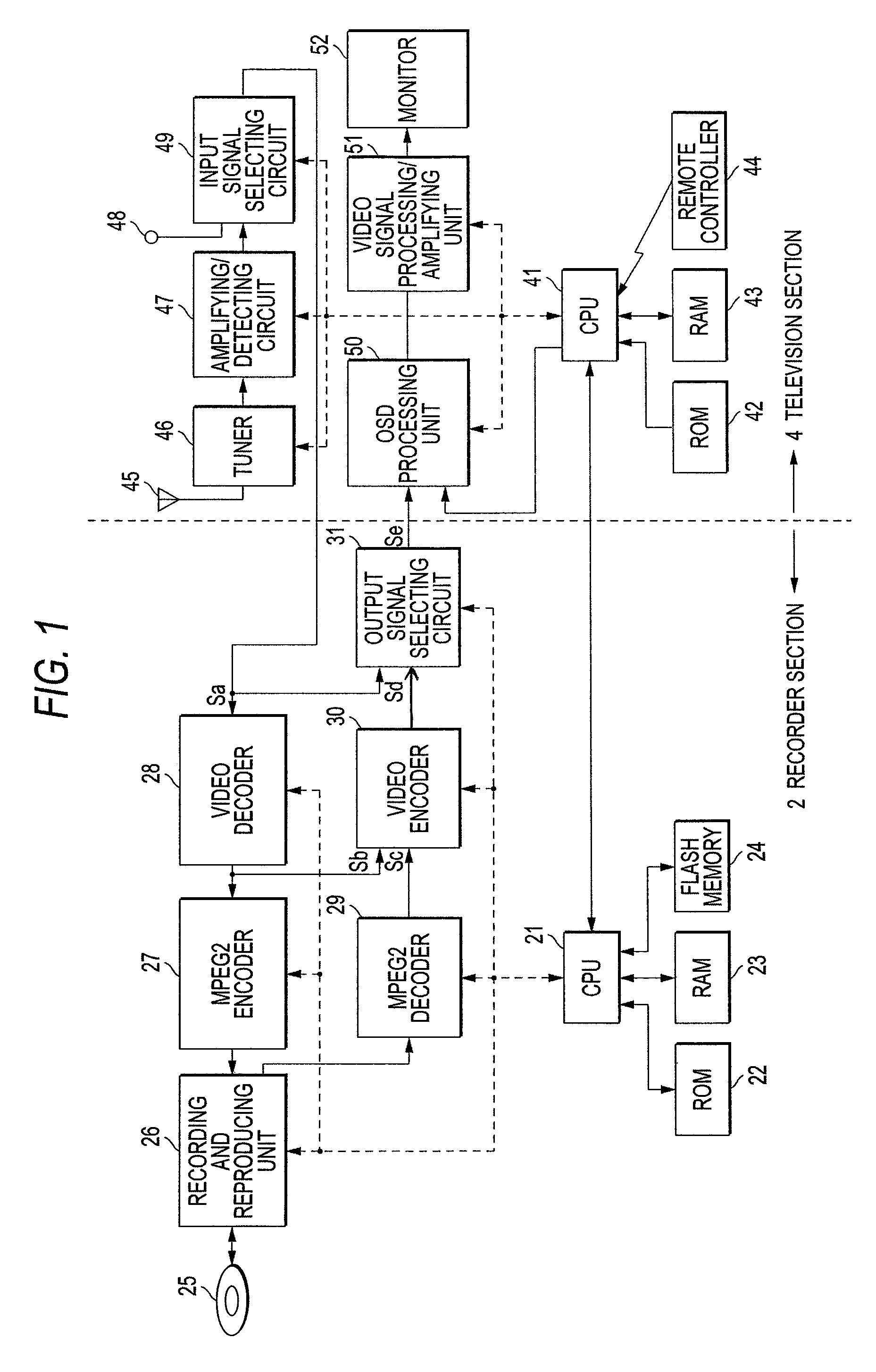
[0019]FIG. 1 is a block diagram showing a television receiver integrated with a DVD recorder (hereinafter, referred to as an apparatus) which is an example of a television receiver integrated with a recording and reproducing apparatus according to the present invention. The apparatus is configured by a DVD recorder section 2 (hereinafter, referred to as a recorder section 2) and a television receiver section 4 (hereinafter, referred to as a television section 4). In FIG. 1, broken lines terminating in arrow heads indicate flows of control signals. Moreover, since a process for television broadcast audio signal is not directly related to the invention, a diagrammatic representation and description thereof will be omitted.

[0020]The recorder section 2 includes a CPU 21, a ROM, a RAM 23, and a flash memory 24. The CPU 21 executes a program stored in the ROM 22 so as to control operations of individual units of the recorder section 2. In addition, the CPU 21 transmits and receives comman...


PUM


Abstract

A television receiver includes: a video decoder that converts a composite signal into a digital signal; a video encoder that converts a reproduced data or the digital signal to output a Y / C signal; a monitor; a detecting unit that detects the reception of broadcast signal; and a controller. When the detecting unit detects that the receiving state is good, the controller controls the video encoder to convert the digital signal so that broadcast pictures are displayed on the monitor by using the Y / C signal. When the detecting unit detects that the receiving state is not good, the broadcast pictures are displayed on the monitor by using the composite signal. When the recording medium is reproduced, the controller controls the video encoder to convert the reproduced data so that reproduced pictures are displayed on the monitor by using the Y / C signal or the component signal.

Description

BACKGROUND OF THE INVENTION[0001]1. Field of the Invention[0002]The present invention relates to a television receiver integrated with a recording and reproducing device.[0003]2. Background Art[0004]As described in Patent Document 1, a television receiver integrated with a DVD recorder according to the related art converts video data recorded on a DVD into an analog video signal, displays reproduced pictures of the DVD on a monitor by using the video signal, and further displays broadcast pictures on a monitor by using a composite signal to be output by a broadcast receiver. In Patent Document 2, a television receiver integrated with a DVD player is described, including a function of preventing burn-in on a monitor screen, which should be handled when still picture reproduction video of DVD or on-screen display is continuously displayed on the monitor. In Patent Document 3, the construction of a television receiver integrated with a videotape recorder is described.[0005][Patent Docu...

Claims


Application Information

Patent Timeline
Patent Type & Authority Patents(United States)
IPC IPC(8): H04N7/64H04N5/94H04N5/91H04N7/01H04N19/89H04N5/44H04N5/64
CPCH04N9/8042H04N5/85H04N9/8715
Inventor YAMASHITA, HIROSHI
Owner FUNAI ELECTRIC CO LTD
Why Eureka
Try Eureka