Broadcast receiver

a receiver and broadcast technology, applied in the field of broadcast receivers, can solve the problems of user irritation, tedious, user task demanding, etc., and achieve the effect of convenient selection

Inactive Publication Date: 2006-01-26
FUNAI ELECTRIC CO LTD
View PDF7 Cites 9 Cited by
  • Summary
  • Abstract
  • Description
  • Claims
  • Application Information

AI Technical Summary

Benefits of technology

[0007] To resolve the conventional shortcomings, one objective of the present invention is to provide a broadcast receiver wherein a new channel to be received can be easily added and set up, and wherein, when the added channel is selected, the best reception state for a broadcast wave can immediately be obtained by a directivity switching antenna.
[0009] As is described above, when a user designates a channel to be added, the controller changes the directivity of the directivity switching antenna to all possible directions and determines in which direction, of all the directions, the broadcast for the pertinent channel can be received and can be reproduced under the best possible conditions, and stores in (adds to) the memory channel information for the added channel and direction information indicating the thus determined direction. By employing this process, the setting up of the added reception channel can be automatically performed within a short period of time. And furthermore, when the channel that has been added is selected for the viewing of a broadcast, the controller can read from the memory the direction information correlated with the channel information for the channel, and can use the direction information to set the direction for the directivity of the directivity switching antenna, i.e., unlike in patent documents 1 to 3, a search (scan) is not performed to obtain the direction for the directivity of the antenna after the channel has been changed. Thus, a broadcast on the new channel can be accepted immediately, under the best possible conditions.
[0011] As described above, when the direction for the directivity is changed (scanned) during the reception of a broadcast, snow (video noise) tends to be displayed or audio noise tends to be output during the scanning. However, when, as described above, a message that the direction for the directivity is being changed is displayed on the display unit, a user can visually confirm that scanning is currently being performed, and this will prevent the user from becoming anxious and fearing that the broadcast receiver may have malfunctioned. It should be noted that the display unit is, for example, a television receiver monitor for a broadcast receiver that receives a television broadcast, or the display panel of a console unit for a television receiver that receives a radio broadcast.
[0013] As described above, channel information that includes information for sub-channels of a channel to be added, and direction information that indicates in which direction, of all the directions available for the directivity of a smart antenna, a digital television broadcast for a channel to be added can be received and can be reproduced under the best possible conditions, are stored in (added to) the memory in correlation with each other. Therefore, by using a remote controller, a desired sub-channel can be easily selected based on the channel information stored in the memory, or more specifically, based on the sub-channel information. In addition, since the sub-channel information and the direction information are stored in the memory in correlation with each other, when a sub-channel is selected, the controller can read, from the memory, the direction information that indicates the direction for the directivity according to which a digital television broadcast for the selected sub-channel can be received under the best possible conditions, and can be used to set the direction information for the smart antenna. As a result, a picture included in the digital television broadcast on the selected sub-channel, having been received under the best possible conditions, can immediately be displayed on the television receiver. Furthermore, when the direction for the directivity of the directivity switching antenna is changed (scanned), a message to that effect is displayed on the television receiver, so that a user can visually confirm that scanning is currently being performed. With this arrangement, even when snow (video noise) is displayed during the scanning, an uneasy feeling that the broadcast receiver may have malfunctioned will not be communicated to a user.
[0014] According to this invention, the addition and setup of a new reception channel can be automatically performed within a short period of time, and when the new channel is selected for reception, abroad cast on the selected channel can immediately be received under the best possible reception conditions.

Problems solved by technology

Therefore, once a channel has been changed, time is required to obtain the best image, a source of irritation for the user.
This is a tedious, demanding user task that is not always performed by all users.

Method used


Image

  • Broadcast receiver
  • Broadcast receiver
  • Broadcast receiver

Examples


Embodiment Construction

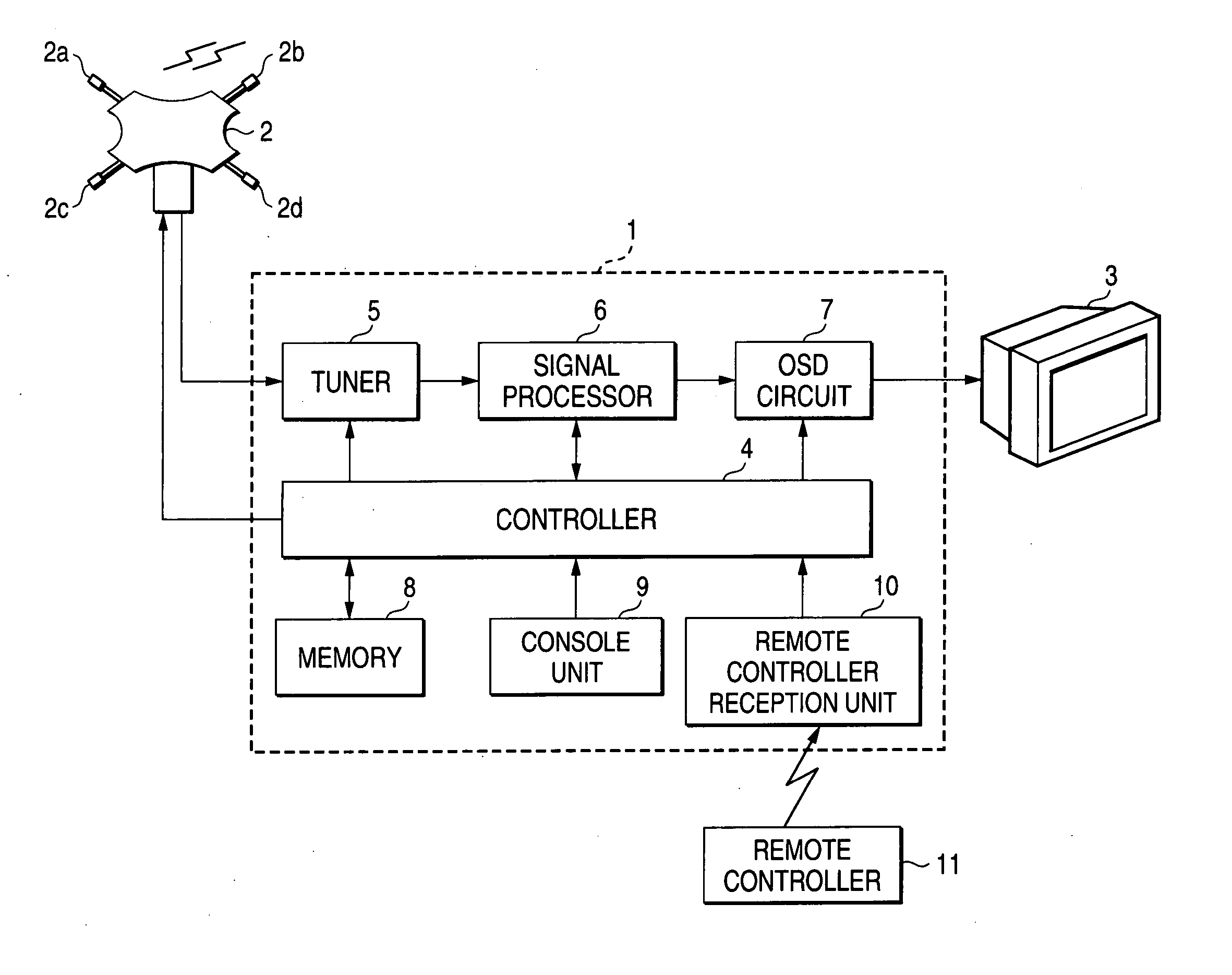
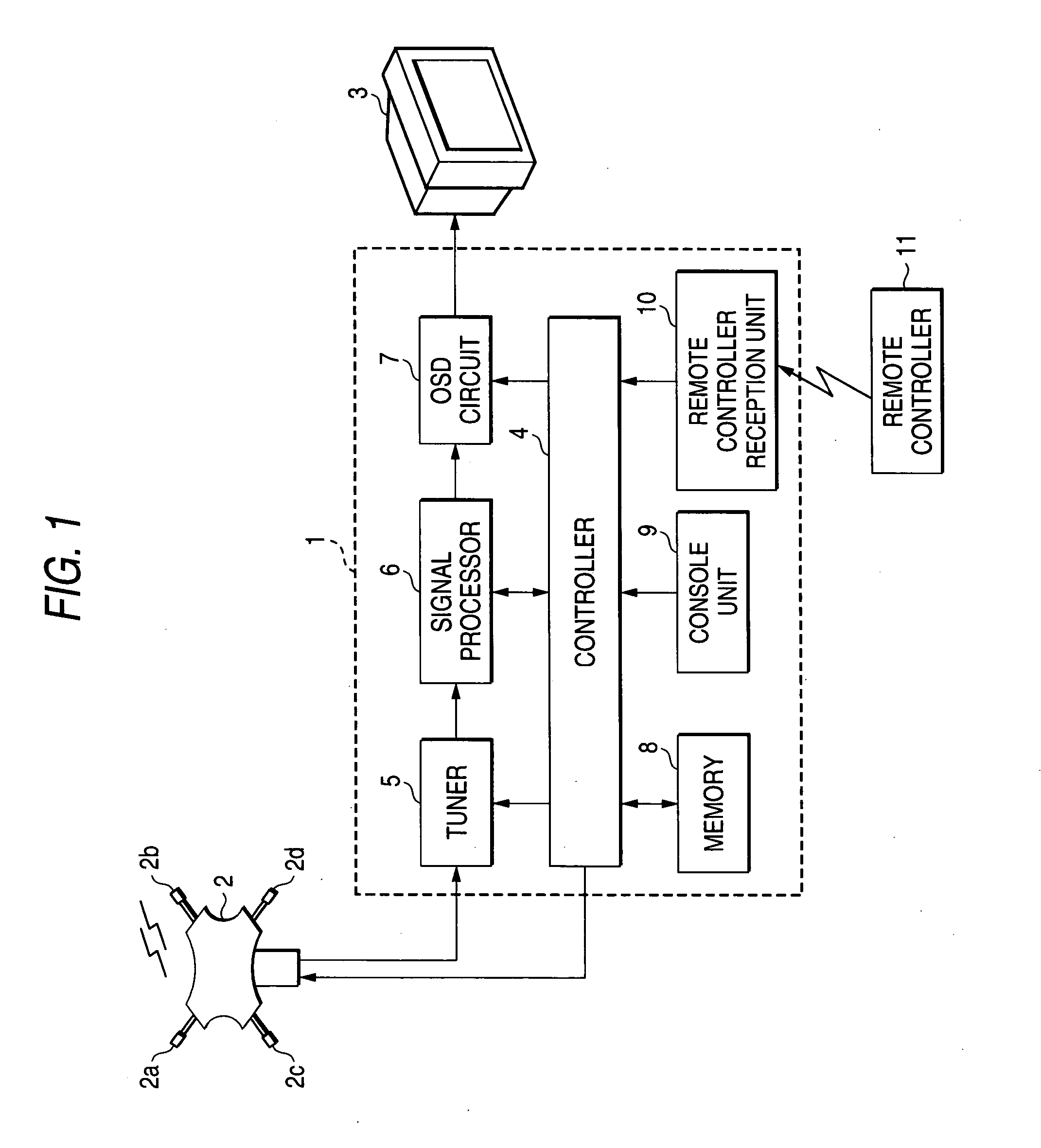
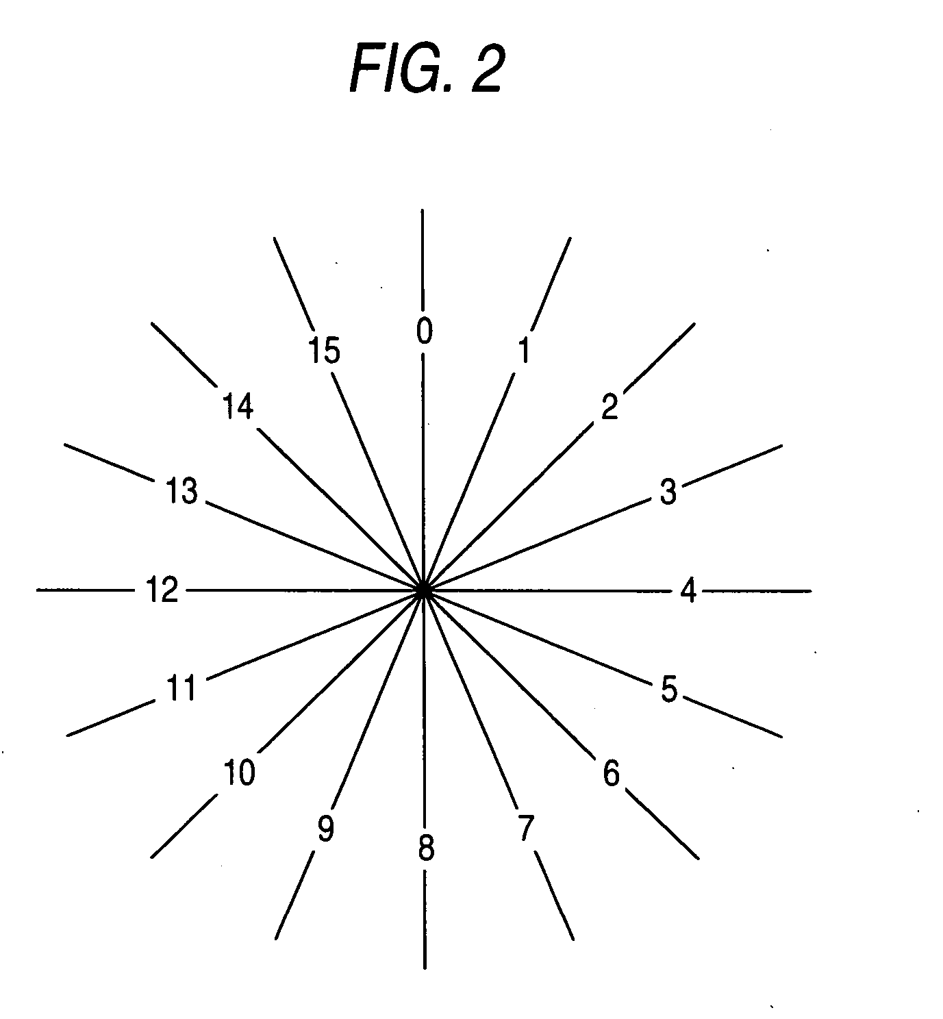
[0022]FIG. 1 is a block diagram showing a television broadcast (hereinafter referred to as a TV broadcast) reception system. A broadcast receiver 1 and a television receiver (hereinafter referred to as a TV 3) 3 are installed in an ordinary house and are connected by a cable. A smart antenna 2 is mounted on the roof of the house and is connected to the broadcast receiver 1 by a cable. The smart antenna 2 is an example antenna (hereinafter referred to as a directivity switching antenna) for which the directivity can be selected, and for this antenna, according to current standards, a direction for the directivity can be selected from among 16 directions available in the surrounding area. The smart antenna 2 includes four antenna devices 2a to 2d, and phase devices, synthesizing devices and control circuits (none of them shown, other than the antenna devices 2a to 2d) that correspond to the antenna devices 2a to 2d. The phases of signals received by the antenna devices 2a to 2d are co...


PUM


Abstract

When a new reception channel is to be added and set, a controller sequentially changes the reception direction for the directivity of a smart antenna and confirms the reception of a broadcast wave in each of the directions. When confirmation of the reception in all the directions has been completed, the controller determines, for the directivity of the smart antenna, in which of the directions the optimal reception and reproduction of the broadcast wave will be provided. When an appropriate direction for the directivity is present, the controller stores the thus determined direction in a channel setup table as part of the data for the channel that is being added. Thereafter, when this channel is selected for the reception of a TV broadcast, the direction determined for the directivity is set for the smart antenna.

Description

BACKGROUND OF THE INVENTION [0001] 1. Field of the Invention [0002] The present invention relates to a broadcast receiver that receives, via a directivity switching antenna, a broadcast on a predetermined channel transmitted by a broadcast station. [0003] 2. Description of the Related Art [0004] In order to improve the property for the reception of a broadcast wave, such as a television broadcast wave, according to one proposal an antenna for which a combination of a plurality of antenna devices can be changed by a switching circuit is connected to a television receiver (hereinafter referred to as a TV), and when the TV is powered on, or when a channel is changed, the signal received for the selected channel is examined while the combination of antenna devices is changed by the switching circuit, and when the best point for the received signal is detected, the switching circuit is fixed (e.g., JP-A-63-42581 (page 2, upper right column, line 13 to page 3, upper left column, line 18))...

Claims


Application Information

Patent Timeline
Patent Type & Authority Applications(United States)
IPC IPC(8): H04N7/173H04B1/16H04B1/18H04N5/44H04N5/445
CPCH04N5/4401H04N5/44513H04N21/4882H04N21/4345H04N21/426H04N5/46H04N21/47
Inventor ONOMATSU, TAKEHIRONARITA, SHUSUKE
Owner FUNAI ELECTRIC CO LTD
Why Eureka
Try Eureka