Placing fiber optic sensor line

a fiber optic sensor and fiber optic technology, applied in the direction of survey, drilling pipe, borehole/well accessories, etc., can solve the problems of insufficient timely data, inability of operators to optimize production, and inability to accurately measure the effect of the sensor lin

Inactive Publication Date: 2005-02-17
WEATHERFORD TECH HLDG LLC
View PDF11 Cites 30 Cited by
  • Summary
  • Abstract
  • Description
  • Claims
  • Application Information

AI Technical Summary

Problems solved by technology

But like many new technologies, successful and reliable development of intelligent well techniques has been a challenge to design.
Although well logs provide valuable information, an inherently costly and risky well-intervention operation is required.
As a result, wells were typically logged infrequently.
The lack of timely data often compromised the ability of the operator to optimize production.
However, the challenge was to develop a cost-effective and reliable solution to integrate permanent-monitoring systems with flow control systems to deliver intelligent wells.
One challenge facing the progress of intelligent completion systems is the development of an efficient and a cost effective method of deploying fiber optic line in the wellbore.
In another example, a load is created on the fiber optic line as it is pumped through the conduit, thereby resulting in possible damage of the fiber optic line.
For example, additional complex equipment, such as the pressure housing apparatus, is required to place the fiber optic line into the wellbore.
In another example, the foam coating on the fiber optic line may not adequately protect the fiber optic line from mechanical forces generated during deployment into the duct, thereby resulting in possible damage of the fiber optic line.
Furthermore, this deployment technique is complex and expensive.

Method used


Image

  • Placing fiber optic sensor line
  • Placing fiber optic sensor line
  • Placing fiber optic sensor line

Examples


Embodiment Construction

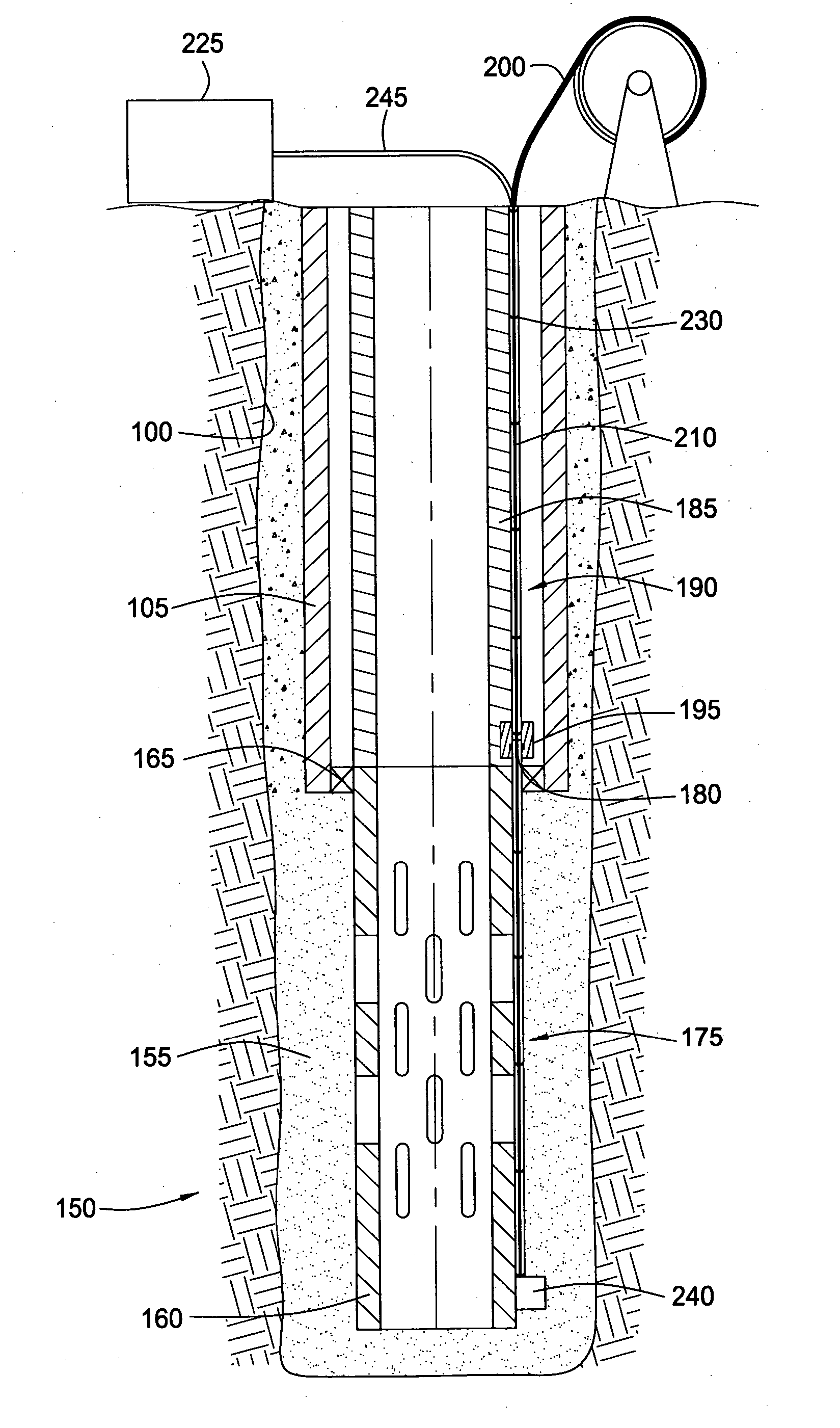
[0022] Embodiments of the present invention generally provide a method and an apparatus for placement of a sensor arrangement in a well, such as fiber optic sensor, to monitor various characteristics of the well. For ease of explanation, the invention will be described generally in relation to a cased vertical wellbore with a sand screen and a gravel pack disposed at the lower end thereof. It is to be understood, however, that the invention may be employed in a wellbore without either a sand screen or a gravel pack. Furthermore, the invention may be employed in a horizontal wellbore or a diverging wellbore.

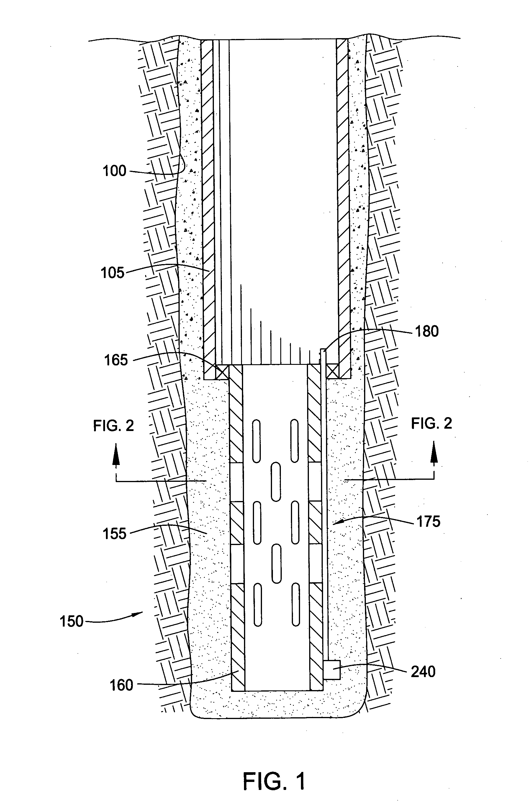
[0023]FIG. 1 is a cross-sectional view illustrating a wellbore 100 with a gravel pack 150 disposed at a lower end thereof. As depicted, the wellbore 100 is lined with a string of casing 105. The casing 105 provides support to the wellbore 100 and facilitates the isolation of certain areas of the wellbore 100 adjacent hydrocarbon bearing formations. The casing 105 typically extend...


PUM


Abstract

The present invention generally relates to a method and an apparatus for placing fiber optic control line in a wellbore. In one aspect, a method for placing a line in a wellbore is provided. The method includes providing a tubular in the wellbore, the tubular having a first conduit operatively attached thereto, whereby the first conduit extends substantially the entire length of the tubular. The method further includes aligning the first conduit with a second conduit operatively attached to a downhole component and forming a hydraulic connection between the first conduit and the second conduit thereby completing a passageway therethrough. Additionally, the method includes urging the line through the passageway. In another aspect, a method for placing a control line in a wellbore is provided. In yet another aspect, an assembly for an intelligent well is provided.

Description

BACKGROUND OF THE INVENTION [0001] 1. Field of the Invention [0002] Embodiments of the present invention generally relate to a wellbore completion. More particularly, the invention relates to placing sensors in a wellbore. Still more particularly, the invention relates to placing fiber optic sensor line in a wellbore. [0003] 2. Description of the Related Art [0004] During the past 10 years decline rates have doubled while at the same time, reservoirs are becoming more complex. Consequently, the aggressive development and installation of new technologies have become essential, such as intelligent well technology. Since downhole measurements play a critical role in the management of oil and gas reservoirs, intelligent well technology has come to the forefront. But like many new technologies, successful and reliable development of intelligent well techniques has been a challenge to design. [0005] Prior to the introduction of permanently deployed in-well reservoir-monitoring systems, th...

Claims


Application Information

Patent Timeline
Patent Type & Authority Applications(United States)
IPC IPC(8): E21B23/08E21B47/12
CPCE21B47/123E21B23/08E21B47/135E21B47/017
Inventor COON, ROBERT J.SETTERBERG, JOHN R. JR.
Owner WEATHERFORD TECH HLDG LLC
Why Eureka
Try Eureka