Assembled floating cover for a storage tank

a floating cover and storage tank technology, applied in the direction of transportation and packaging, packaging, large containers, etc., can solve the problems of inconvenient mounting, difficult fabrication, and complex construction, and achieve the effect of reducing maintenance time, increasing the amount of oil to be reserved, and lightening weigh

Inactive Publication Date: 2005-02-17
ZIBO OCEANUS ZHANG FLOATING PLATE TECHN DEV
View PDF3 Cites 5 Cited by
  • Summary
  • Abstract
  • Description
  • Claims
  • Application Information

AI Technical Summary

Benefits of technology

[0003] The object of the invention is to provide a built-up outer floating disc for oil reservoir such that the above disadvantages can be avoided. The outer floating disc has a skeleton composed of bolt-joined components with I-shaped profile made from steel plates and connected by bolts. It has no the disadvantage of leak from weld, so that the accident of sinking down of the disc does not happen. Its perimeter is sealed with a double layer structure, one of tongue-shaped sealing rubber band and another of capsule-like sealing rubber band, it is not liable to be worn, so that the time for maintenance can be reduced. The floaters are laid over all the space within the skeleton, they are thin enough that the amount of oil to be reserved can be increased. In addition, the floaters are made from non-metallic material which has a lighter weight, so the consumption of metallic material can be reduced.

Problems solved by technology

This construction is rather complex, difficult to fabricate and inconvenient to mount.
As its seams are liable to leak, the disc is liable to sink down.
On the other hand, as the vertical motion of floating disc is guided by columns, in the case in which the center of gravity is shifted, the disc is liable to block on its way, which also leads to sink down.
Besides, a capsule-like sealing rubber band is used on the perimeter of outer floating disc, the band is liable to be worn owing to its large coefficient of friction, both maintenance and replacement of the band are time-consuming.

Method used


Image

  • Assembled floating cover for a storage tank
  • Assembled floating cover for a storage tank

Examples


Embodiment Construction

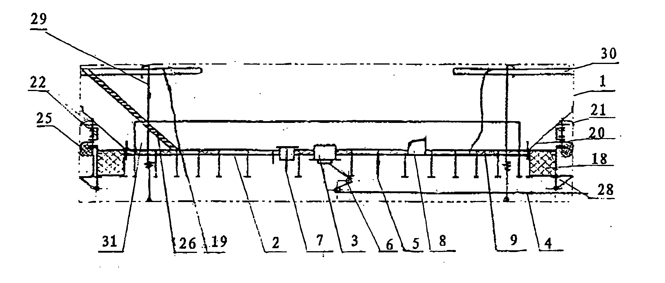
[0008] It can be seen from FIG. 1, within the body (1) of reservoir, there mounts an outer floating disc (2). At its central position, there mounts a central water draining funnel (3) which is connected with a lower water draining pipe (4). At the bottom of outer floating disc (2), there mount several supporting legs (5), and an emergency water discharging valve (6). At the central position of the disc, there further mounts a safety venting valve (7). On the upper face of outer floating disc (2), there provides a manhole (8) for inspection and repair. On the body of the floater, there further mounts a fire-extinguishing foam protecting plate (31). And over the top of body (1) of the reservoir, a supporting frame (30) is installed.

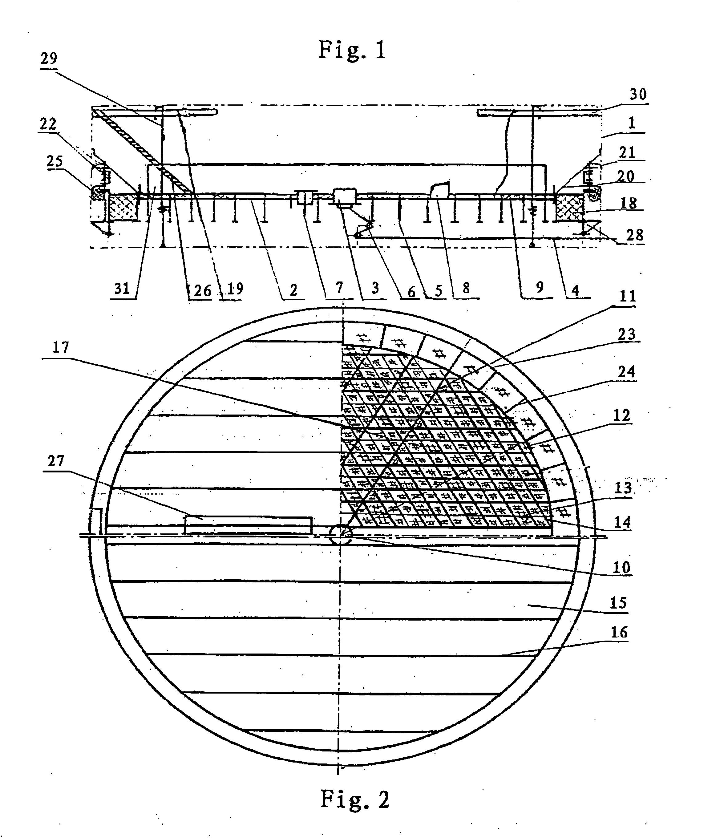
[0009] It can be seen from FIG. 2, the components with I-shaped profile are made from steel plate and joined by bolts into a radiant skeleton structure, the floaters (9) made from oil resistant hard poly-urethane plastics are light and are laid full of the...


PUM


Abstract

A built-up floating disc for oil reservoir concludes an inner floating disc and an outer floating disc. The inner and outer floating discs both have a radiant skeleton structure composed of bolt-joined components with I-shaped profile made from steel plate or aluminum plate. There are 6 radial beams connected with a central plate and annular beams. Peripheral beams are used to connect between the outer annular beam and the inner annular beams. Coverplate fixed beams are mounted on the radial beams, auxiliary beams are used to connect between coverplate fixing beams. Plastic floaters presenting equilateral friangle or parallelogram in shape are laid over the space within the skeleton. Thick floaters are secured on the outer annular beam and the inner annular beam. Coverplates are laid on the coverplate fixed beams and are clamped by press bars. A tongue shaped sealing rubber band and a capsule-like sealing rubber band constitute a double layer structure. Using the floating disc can prevent reserved oil from contamination and degradation. And the floating disc is lighter, it can reduce the consumption of metallic material and eliminate the phenomena of sinking disc and blocking disc.

Description

TECHNICAL FIELD [0001] The invention relates to a built-up outer floating disc for oil reservoir and pertains to the technical field of equipment for oil reservation and transportation. BACKGROUND OF ART [0002] It is common practice to provide a floating disc in the oil reservoir, in order to prevent the oil from contamination and degradation and further to diminish evaporation loss of the oil. CN 88201602 has recommended an inner floating disc which has a radiant skeleton structure composed of bolt-jointed components with I-shaped profile made from steel plates, and within the skeleton, plastic floaters are arranged in a ring form. CN 90222242.5 has provided an antistatic floater which is composed of a plurality of equilateral triangular components with a top angle of 30°. This construction is rather complex, difficult to fabricate and inconvenient to mount. Furthermore, there is a conventional outer floating disc which is welded from steel plates. As its seams are liable to leak, ...

Claims


Application Information

Patent Timeline
Patent Type & Authority Applications(United States)
IPC IPC(8): B65D88/34B65D88/42
CPCB65D88/42B65D88/34
Inventor ZHANG, FENGQIU
Owner ZIBO OCEANUS ZHANG FLOATING PLATE TECHN DEV
Why Eureka
Try Eureka