
Remotely controllable revolving support for speaker

Inactive Publication Date: 2005-02-17
COLEMAN LUDLOW PETER
View PDF38 Cites 19 Cited by
  • Summary
  • Abstract
  • Description
  • Claims
  • Application Information

AI Technical Summary

Benefits of technology

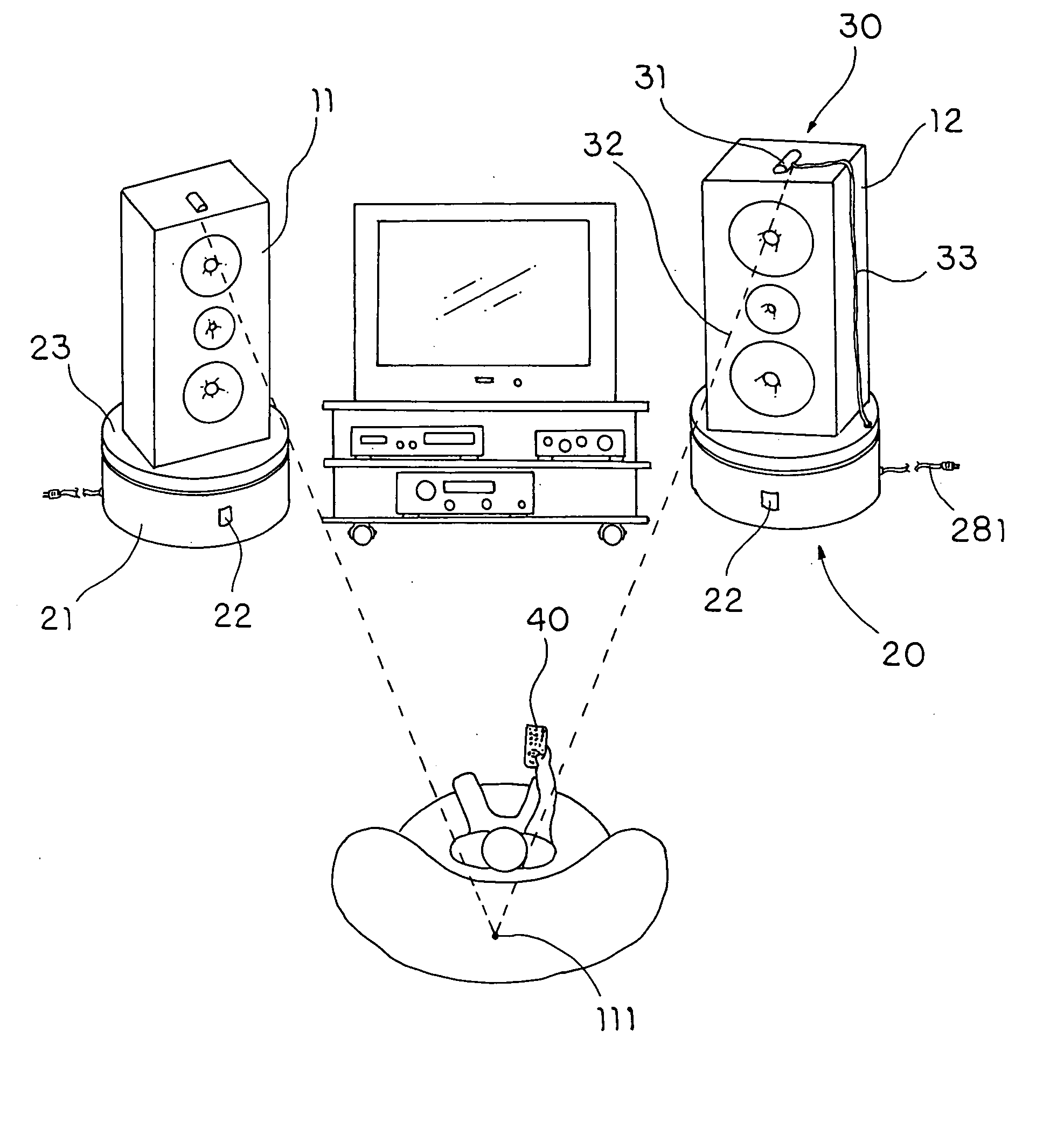
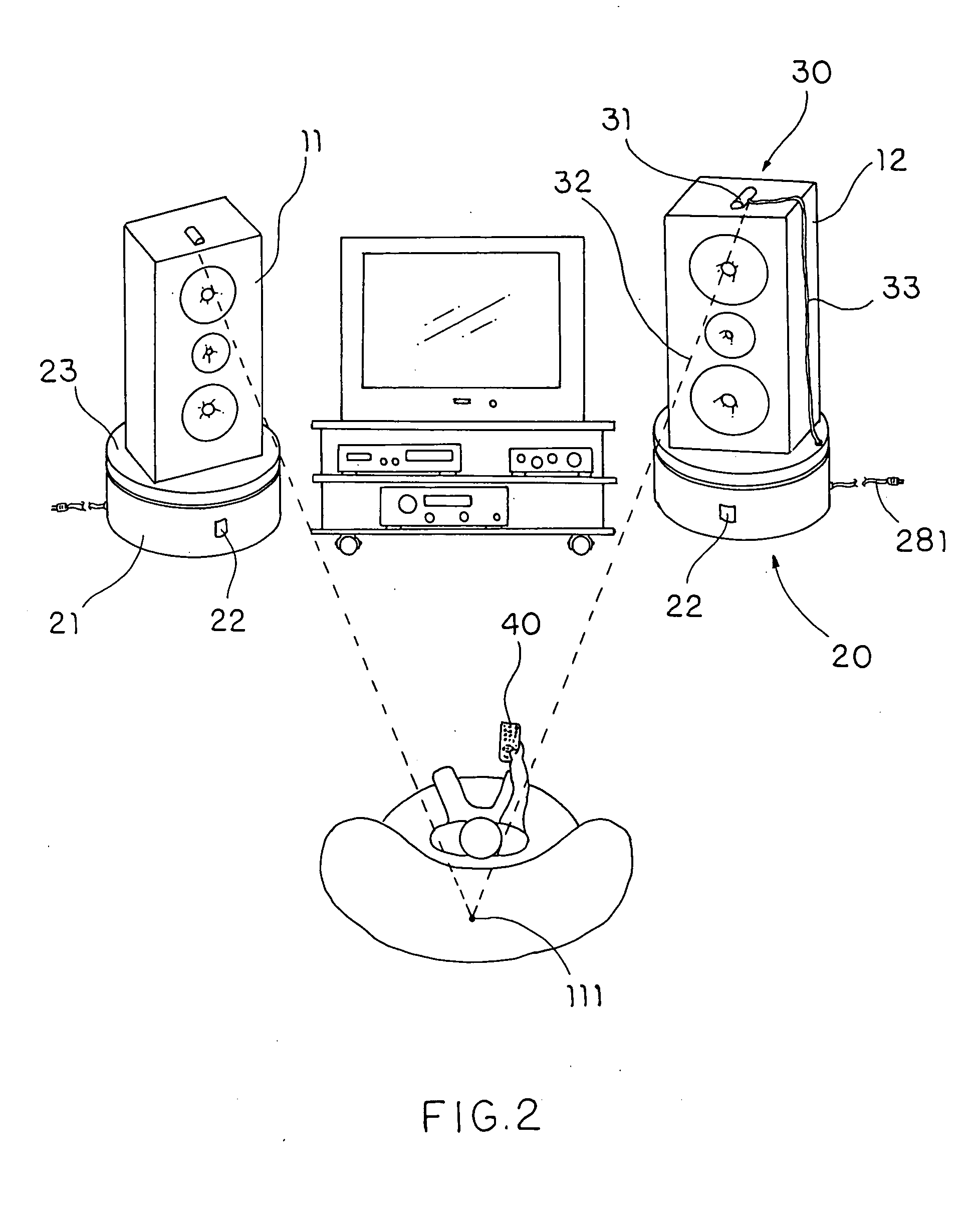
[0011] The main object of the invention is to provide a revolving support for speaker which is able to be driven to revolve by a motor under a control of a remote control, enabling a user adjust a direction of the speaker while sitting in a seat.
[0012] Another object of the invention is to provide a revolving support for speaker which has an indicating means being able to clearly indicate the direction towards which the speaker is facing thus enabling a user easily and accurately identifies a sweetspot of more than one speaker.

Problems solved by technology

For some speakers light in weight and rarely moved, the task may be trivial.
Such action may be repeated several times. However for some other speakers that are as heavy as from tens up to hundreds of pounds and that frequently need to be relocated, such as the ones used on stage or for temporary performance, to rotate the speakers by hands become a very difficult, sometimes even an impossible, task.
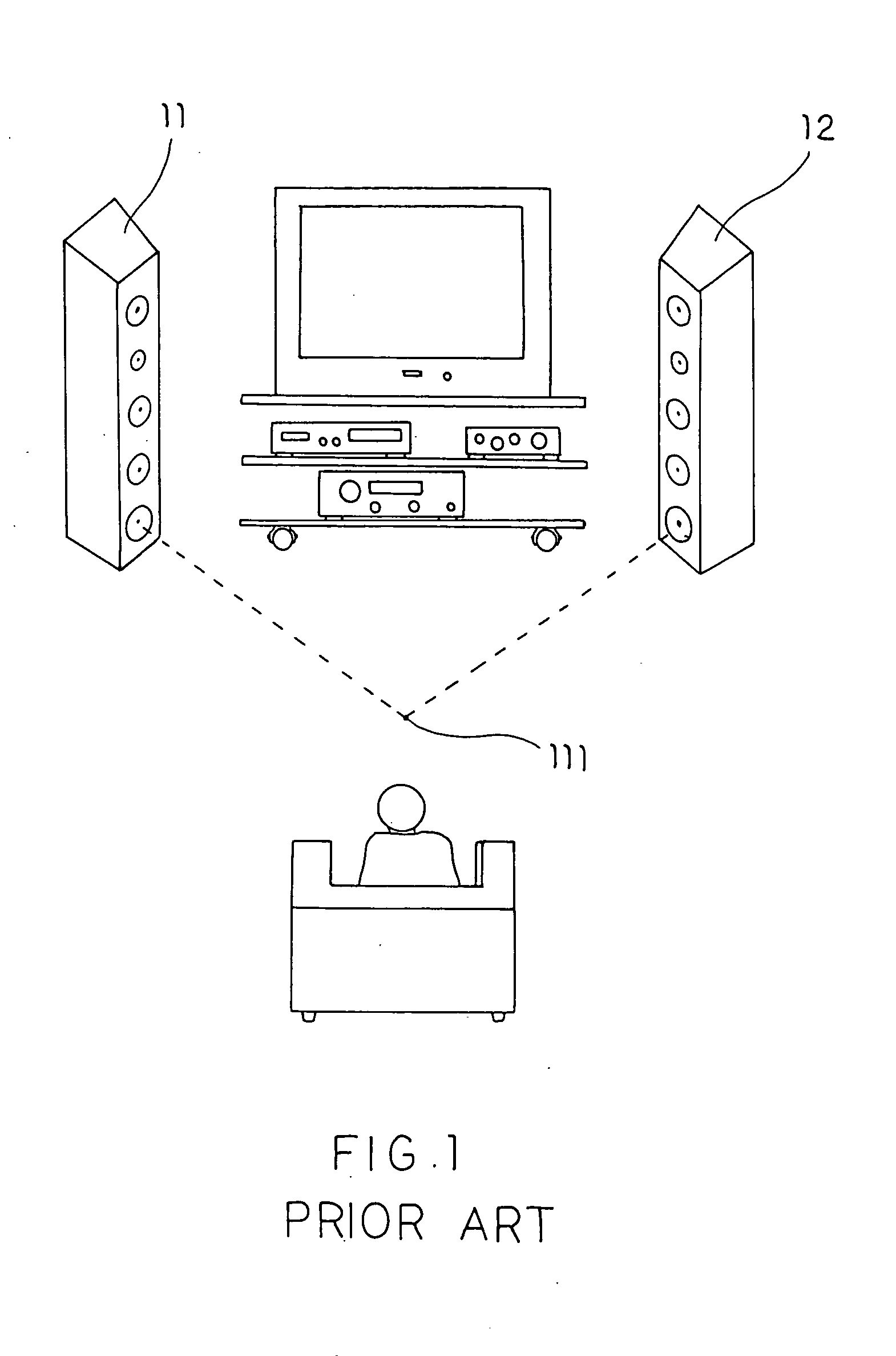
It is noteworthy that in aforementioned adjusting, the user usually finally compromises on a make-do result because to continue is so force-taking and, at the same time, he does not have any indicator help him clearly determine whether the sweetspot 111 is really reached.
However no one choice is really satisfactory.
The first one not only increases the workload of finding a sweetspot 111 but also brings risk of falling down.
The third may be the worst one since no one would like to tolerate poor sound effect if they can get better.

Method used


Image

  • Remotely controllable revolving support for speaker
  • Remotely controllable revolving support for speaker
  • Remotely controllable revolving support for speaker

Examples


Embodiment Construction

[0025] Referring to FIG. 2 of the drawings, two speakers 11, 12 rotatably and respectively supported by two remotely controllable revolving supports 20 according to a preferred embodiment of the present invention is illustrated, wherein the two speakers 11, 12 are placed apart from each other at a certain distance in front of a user. Each speaker 11, 12 is positioned above the respective revolving support 20 which comprises a base housing 21 securely standing on a ground surface, and a revolving platform 23 rotatably supported on the base housing 21 in such a manner that it is adapted to rotate with respect to the base housing 21 for delivering sound to a sweetspot of the two speakers 11, 12. Moreover, the revolving support 20 further comprises a remote control 40 which is arranged to generate a remote control signal, such as an infrared control signal, and a remote sensor, such as an infrared sensor 22, installed in a side wall of the base housing 21 for sensing and receiving the i...


PUM


Abstract

A revolving support for a speaker includes a base housing, a revolving platform, a motor plinth, and a control circuit. The revolving platform is rotatably provided on the base housing, wherein the speaker is adapted to securely rest on the revolving platform. The motor plinth is disposed in the base housing, and includes a motor operatively communicated with the revolving platform in such a manner that the motor is arranged to drive the revolving platform rotating with respect to the base housing. The control circuit is electrically connected with the motor in such a manner to controllably activate the motor to drive the revolving platform rotating with respect to the base housing, such that the revolving platform is adapted to turn and align the speaker to a predetermined optimal orientation for delivering a maximum sound quality in the direction.

Description

CROSS REFERENCE OF RELATED APPLICATION [0001] This is a regular application of a provisional application Ser. No. 60 / 490,822, filed Jul. 28, 2003 by the inventor of this application.BACKGROUND OF THE PRESENT INVENTION [0002] 1. Field of Invention [0003] The invention relates to a revolving support for speaker, especially to a support a direction thereof is able to be adjusted by a remote control thus helping a user easily find a sweet point for better enjoyment in stead of turning the speaker by hands which is both force-taking and inaccurate. [0004] 2. Description of Related Arts [0005] Persons who care of enjoying sound of speakers and who have used speakers know that a direction of speaker is a very important factor in the enjoyment. As shown in FIG. 1, when there are more than one speaker 11, 12, as a common situation goes, imaginary lines respectively vertical with respect to each speaker 11, 12 would better converge at a point called as “sweetspot”111. Persons may have such ex...

Claims


Application Information

Patent Timeline
IPC IPC(8): F16M11/08F16M11/18
CPCF16M11/08F16M2200/08F16M11/18
Inventor COLEMAN, LUDLOW PETER
Owner COLEMAN LUDLOW PETER
Learn More