

In-line roller skate braking mechanism
a braking mechanism and in-line roller skate technology, applied in the field of skates, can solve the problems of inability to stop efficiently, inability to quickly and efficiently stop and inability to stop quickly and efficiently like an in-line roller ska
Inactive Publication Date: 2005-02-17
KRIVULIN ARKADIY
View PDF10 Cites 8 Cited by
- Summary
- Abstract
- Description
- Claims
- Application Information
AI Technical Summary
Benefits of technology
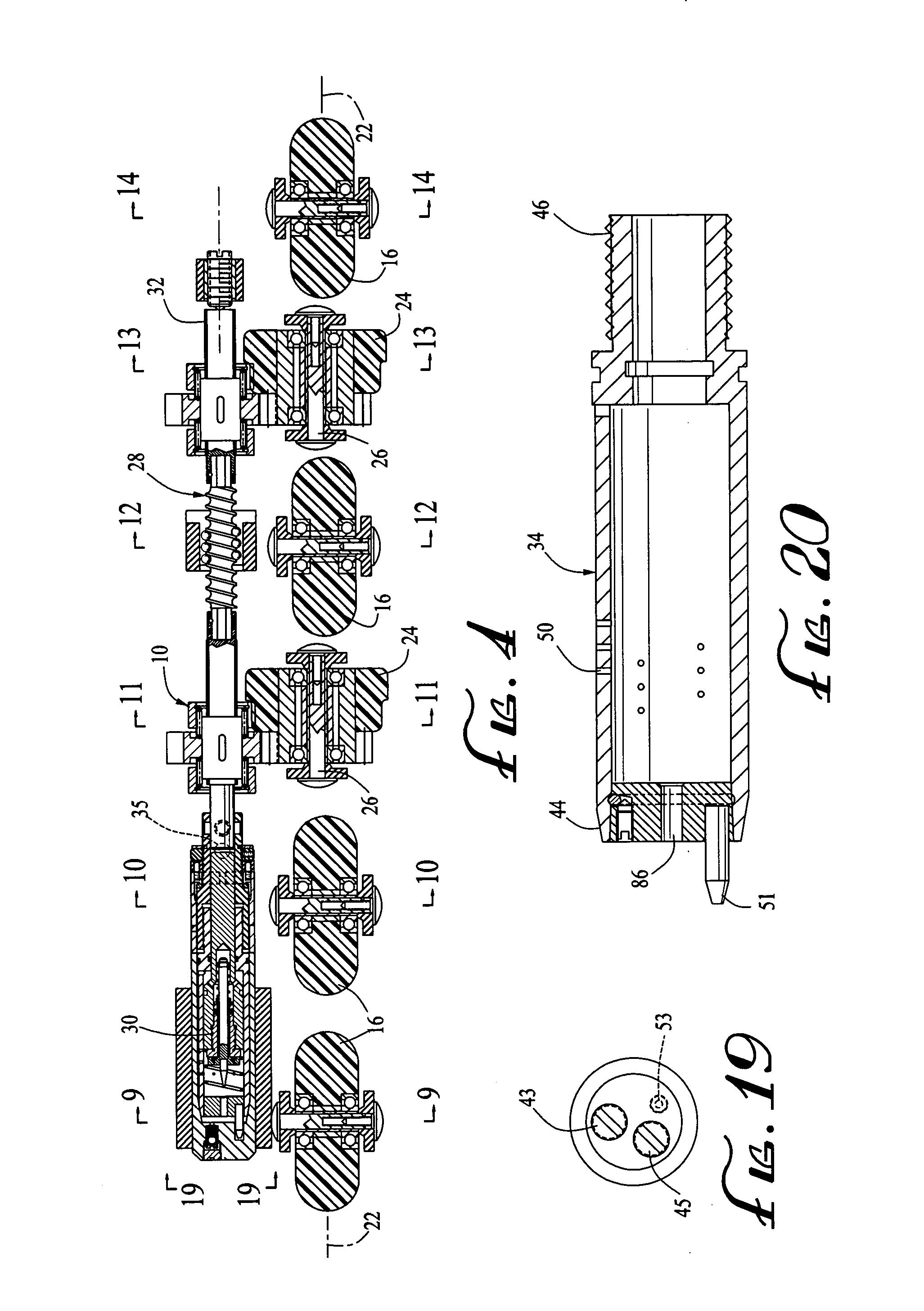
[0004] The invention is a braking system for a skate, such as an in-line roller skate. Typically, such a skate has a base skating surface with a base skating surface longitudinal axis. The braking mechanism comprises (a) at least one braking wheel disposed above the base skating surface, the at least one braking wheel being rotatable about a braking wheel axis disposed in a vertical plane, the vertical plane intersecting the base skating surface longitudinal axis at an angle of between about −20° and about +20°; (b) a piston housing having piston housing side walls, a first piston housing section proximal to a first piston housing end and a second piston housing section distal to the first piston housing end, the first piston housing section defining a plurality of first piston housing section side wall apertures, the first piston housing section side wall apertures being disposed at a plurality of different distances from the piston housing first end, the second piston housing section comprising one or more second piston housing section side wall apertures; (c) a piston disposed within the piston housing, the piston having a first end and a second end, the first end comprising an internal piston flow channel and a slide valve disposed in the first end of the piston for controlling the flow of liquid from the piston flow channel to the first piston housing section, the piston further comprising one or more piston inlet channels for allowing the flow of liquid into the piston flow channel from the second piston housing section, the piston being mechanically connected to the at least one braking wheel such that the rotation of the at least one braking wheel moves the piston within the piston housing between (i) a first piston position wherein the piston is distal from the first piston housing end and wherein the piston is not adjacent to the first piston housing section side wall apertures, and (ii) a second piston position wherein the piston is proximal to the first piston housing end and the piston is adjacent to some or all of the first piston housing section side wall apertures, the slide valve being adapted to close when the piston is moved from the first piston position to the second piston position and to open when the piston is moved from the second piston position to the first piston position; (d) a first biasing mechanism for urging the piston towards the first piston position; (e) sealing means for sealing the piston within the piston housing such that (i) liquid disposed in the first piston housing section cannot leak around the piston to the second piston housing section, and (ii) when the piston is moved adjacent to one of the plurality of first piston housing section side wall apertures, liquid disposed in the first piston housing section cannot leak around the piston and out through that first piston housing section side wall aperture; and (f) an external flow channel having a first end a second end, the first end of the external flow channel being in fluid tight communication with the first piston housing section via the first piston housing section side wall apertures, the second end of the external flow channel being in fluid tight communication with the second piston housing section via the second piston housing section side wall apertures; whereby, (i) when a liquid is disposed within the first piston housing section, the application of an axial force to the braking wheel causes the rotation of the at least one braking wheel and its braking wheel axis to thereby move the piston from the first piston position towards the second piston position, the slide valve is closed and the piston pressurizes liquid out of the first piston housing section via the first piston housing section side wall apertures, and into the second piston housing section via the second piston housing section side wall apertures, and (ii) when the axial force on the at least one braking wheel is released, the first biasing means urges the piston from the second piston position towards the first piston position, the slide valve is opened and liquid returns to the first piston housing section from the second piston housing section via the piston flow channel.
Problems solved by technology
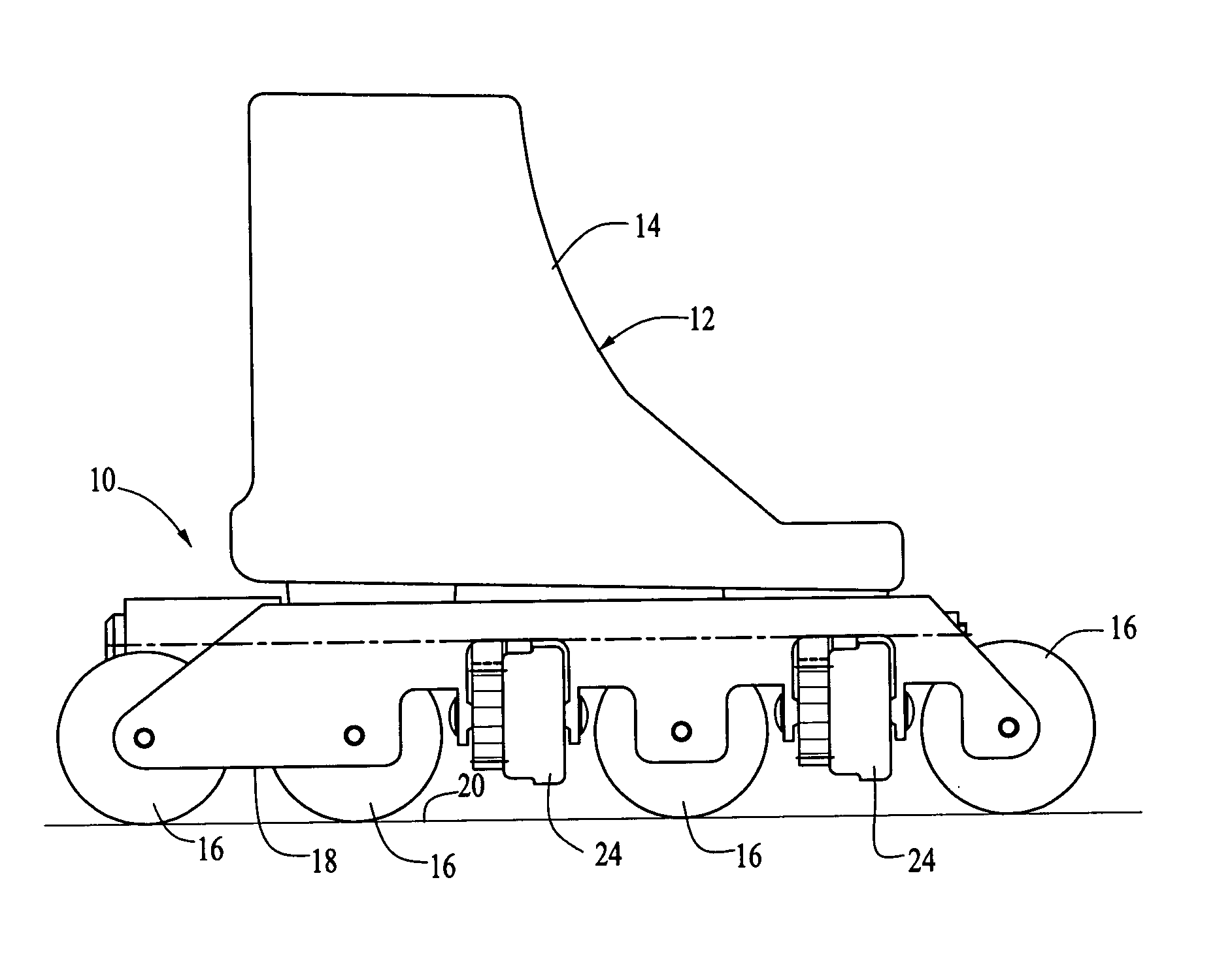
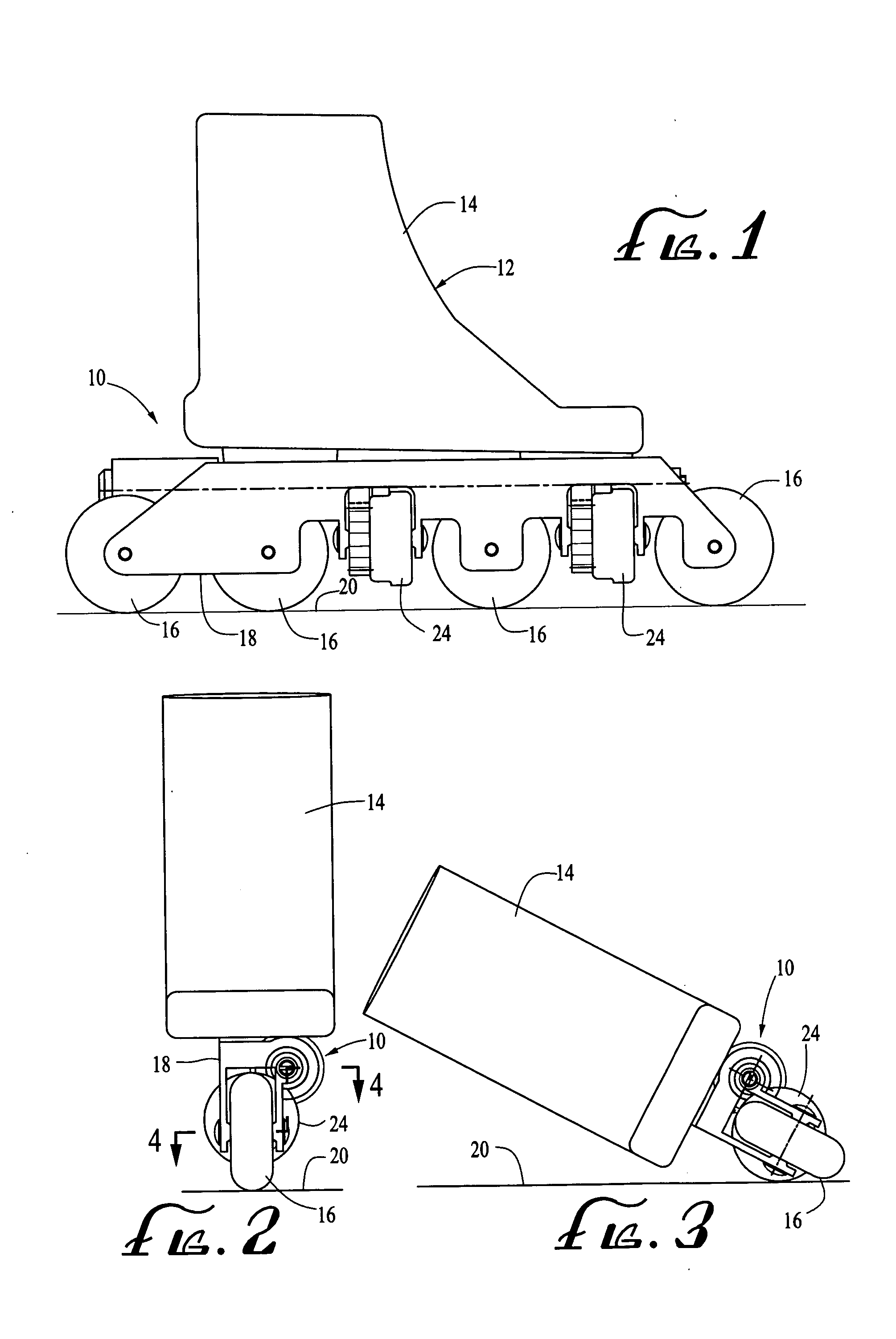
A problem persists with respect to in-line roller skates, however, regarding the inability of an in-line roller skate to stop efficiently as can an ice skate.
In-line roller skates cannot stop quickly and efficiently like ice skates, because in-line roller skates cannot brake by turning one or, preferably, both of the skates transverse to the direction of travel.
Method used
View moreImage
Smart ImageViewing Examples

Examples
example
[0059] In one illustrative example of the invention, a boot 14 of a size 10 has skating wheels 16 with diameters of 72 mm. The diameters of the braking wheels 24 are 57 mm. The distance between the braking wheels 24 and the base skating surface 20 is 14.85 mm, the first piston housing section side wall apertures 50 have diameters of 0.79 mm and are 18 in number. The second piston housing section side wall apertures 52 have diameters of 1.6 mm and are 6 in number. The diameter of the piston housing end wall aperture 86 is 2.78 mm. The piston inlet channels 58 have a diameter of 1.6 mm and are 6 in number.
Login to View More PUM
 Abstract
A braking mechanism for a skate, such as an in-line roller skate, has at least one braking wheel disposed transverse to the skate boot. The braking wheel operates a piston which displaces liquid from a piston housing when the piston is caused to travel within the piston housing by the rotation of the braking wheel. The piston and the piston housing are configured such that an increasing resistance is applied to the rotation of the braking wheel as the piston travels within the piston housing. Thus, when the skate boot is turned transverse to the direction of the skater and the angle of the boot is adjusted to cause the braking wheel to rotate, the increased resistance to the rotation of the braking wheel as the piston moves within the piston housing acts to slow the skater. When the piston fully traverses the piston housing, the rotation of the braking wheel is terminated and the skater comes to a stop.
Description
FIELD OF THE INVENTION [0001] This invention relates generally to skates and, more particularly, to braking mechanisms for skates, especially for in-line roller skates. BACKGROUND OF THE INVENTION [0002] In-line roller skates have become very popular. A problem persists with respect to in-line roller skates, however, regarding the inability of an in-line roller skate to stop efficiently as can an ice skate. In-line roller skates cannot stop quickly and efficiently like ice skates, because in-line roller skates cannot brake by turning one or, preferably, both of the skates transverse to the direction of travel. [0003] Accordingly, there is a need for a braking mechanism for in-line roller skates which avoids this problem in the prior art. SUMMARY OF THE INVENTION [0004] The invention is a braking system for a skate, such as an in-line roller skate. Typically, such a skate has a base skating surface with a base skating surface longitudinal axis. The braking mechanism comprises (a) at ...
Claims
Login to View More Application Information
Patent Timeline
 Patent Type & AuthorityApplications(United States)
IPC IPC(8): A63C17/14
CPCA63C17/06A63C2203/02A63C2201/02A63C17/1445
InventorKRIVULIN, ARKADIY
OwnerKRIVULIN ARKADIY