Inkjet head

a technology of inkjet head and inkjet printing, which is applied in the direction of printing and inking apparatus, etc., can solve the problems of crosstalk having a bad influence on the ink ejection from the required pressure chamber, and achieve the effect of preventing crosstalk

Active Publication Date: 2005-02-17
BROTHER KOGYO KK
View PDF4 Cites 16 Cited by
  • Summary
  • Abstract
  • Description
  • Claims
  • Application Information

AI Technical Summary

Benefits of technology

[0005] When a plurality of pressure chambers are arranged adjacently to achieve high-density printing in the inkjet head described in JP-A-11-34323, each land portion is however located relatively near to the main electrode regions of adjacent individual electrodes because each land portion is provided on the outside of the region of the piezoelectric sheet opposite to a corresponding pressure chamber. On the other hand, a diaphragm serving as the common electrode has regions opposite to the land portions respectively and is arranged so as to

Problems solved by technology

The deformation exerts influence on distortional deformation of the piezoelectric sheet at regions opposite to the main electrode regio

Method used


Image

  • Inkjet head
  • Inkjet head
  • Inkjet head

Examples


Embodiment Construction

[0033] Embodiments of the invention will be described below with reference to the drawings.

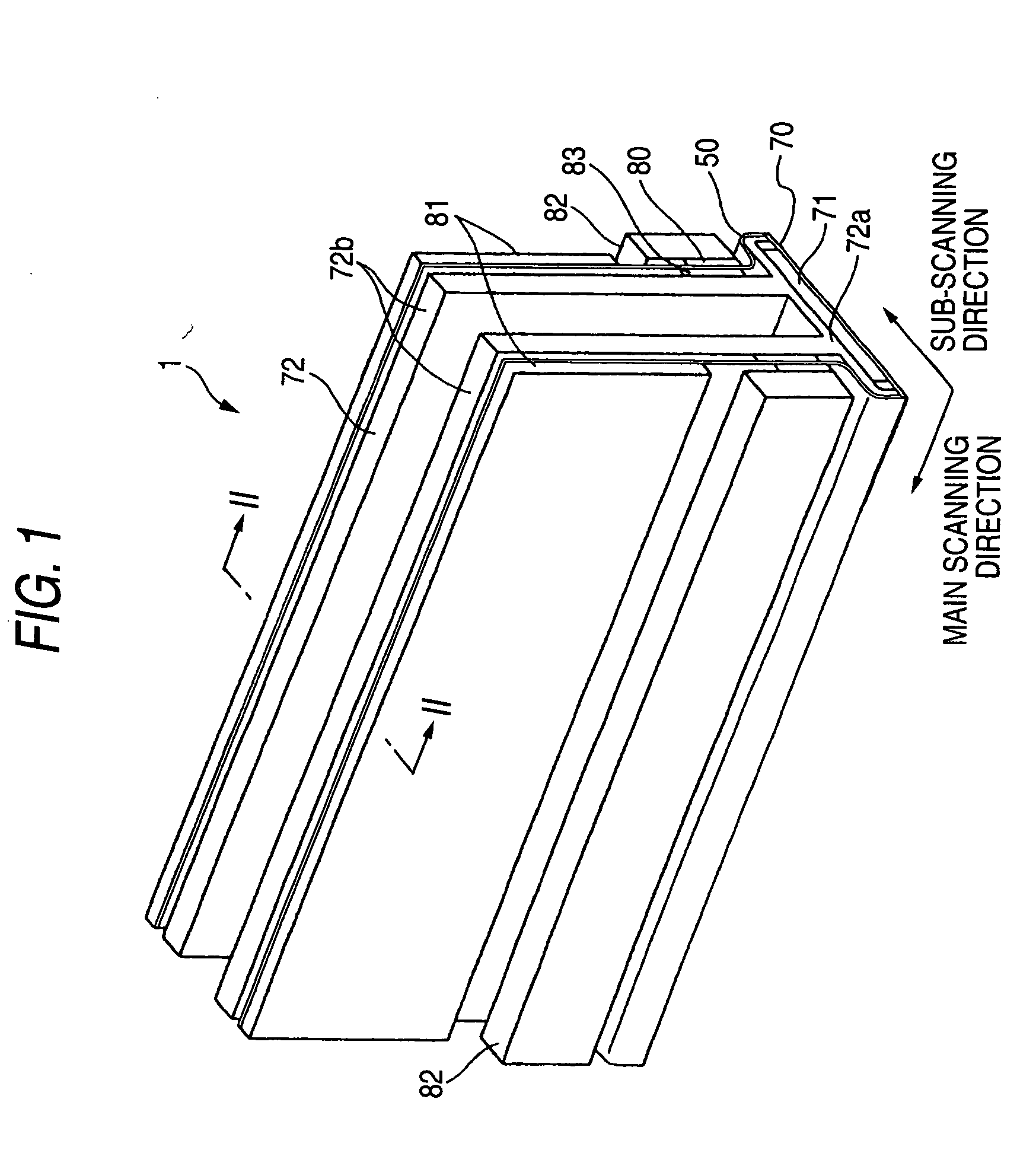
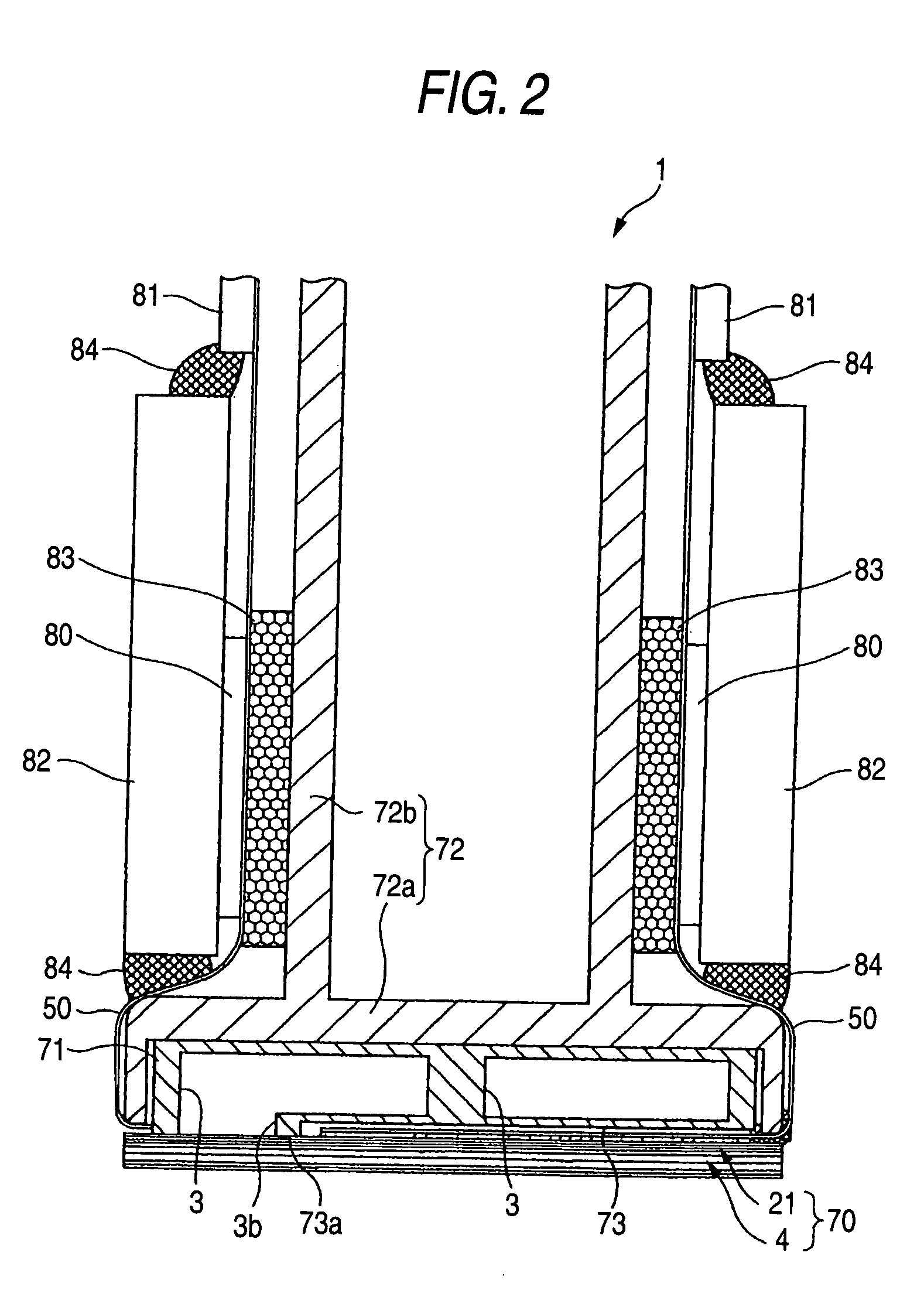
[0034]FIG. 1 is a perspective view showing the external appearance of an inkjet head according to an embodiment of the invention. FIG. 2 is a sectional view taken along the line II-II in FIG. 1. The inkjet head 1 has a head body 70, and a base block 71. The head body 70 extends in a main scanning direction so as to be shaped like a rectangle in plan view for ejecting ink onto a sheet of paper. The base block 71 is disposed above the head body 70 and includes ink reservoirs 3 which are flow paths of ink supplied to the head body 70.

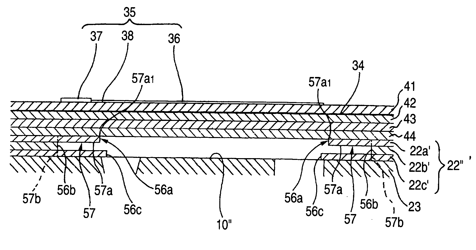
[0035] The head body 70 includes a flow path unit 4, and a plurality of actuator units 21. Ink flow paths are formed in the flow path unit 4. The plurality of actuator units 21 are bonded onto an upper surface of the flow path unit 4. The flow path unit 4 and actuator units 21 are formed in such a manner that a plurality of sheet members are laminated and bonded to...


PUM


Abstract

An inkjet head includes an actuator unit, and a flow path unit. Individual electrodes are formed on a piezoelectric sheet of the actuator unit. Pressure chambers are formed in a cavity plate of the flow path unit. Each individual electrode has a main electrode region disposed in a position opposite to a corresponding pressure chamber, and a land portion connected to the main electrode region. Overhang portions protruding in a direction along a surface of the cavity plate are formed in side walls of each pressure chamber. Each land portion at least partially overlaps a corresponding overhang portion at a height level (top height level) of a contact surface between the cavity plate and the actuator unit.

Description

BACKGROUND OF THE INVENTION [0001] 1. Field of the Invention [0002] The present invention relates to an inkjet head used in an inkjet recording apparatus which ejects ink onto a recording medium to perform printing. [0003] 2. Description of the Related Art [0004] In an inkjet head described in JP-A-11-34323 (Page 3, FIG. 1), each of individual electrodes (upper electrodes) separately formed in accordance with pressure chambers (pressurizing chambers) respectively has a main electrode region (body) formed in a planar direction parallel to a piezoelectric sheet (piezoelectric film) so as to be smaller than a corresponding pressure chamber, and an extension portion extending from the main electrode region to the outside of the pressure chamber region. A land portion, which serves as a point of contact with another member, is provided in a position of the extension portion on the outside of the pressure chamber region. Another member such as wiring is connected to the land portion by so...

Claims


Application Information

Patent Timeline
IPC IPC(8): B41J2/045B41J2/055B41J2/14
CPCB41J2/14209B41J2002/14217B41J2202/20B41J2002/14306B41J2002/14459B41J2002/14225B41J2002/14491
Inventor WATANABE, HIDETOSHI
Owner BROTHER KOGYO KK
Why Eureka
Try Eureka