Lamp

Inactive Publication Date: 2005-02-17
KOSHER INNOVATIONS LTD
View PDF6 Cites 22 Cited by
  • Summary
  • Abstract
  • Description
  • Claims
  • Application Information

AI Technical Summary

Benefits of technology

[0005] The subject lamp reduces the inconvenience caused by a lamp that remains electrically turned on

Problems solved by technology

This can force a family to leave some lights on during this period, howev

Method used


Image

  • Lamp
  • Lamp
  • Lamp

Examples


Embodiment Construction

[0015] Broadly, the lamp allows the escape of heat even when light from the lamp is blocked. In this regard, the lamp may have a moveable shade body providing a selectively sized aperture for allowing emission of a selective amount of light.

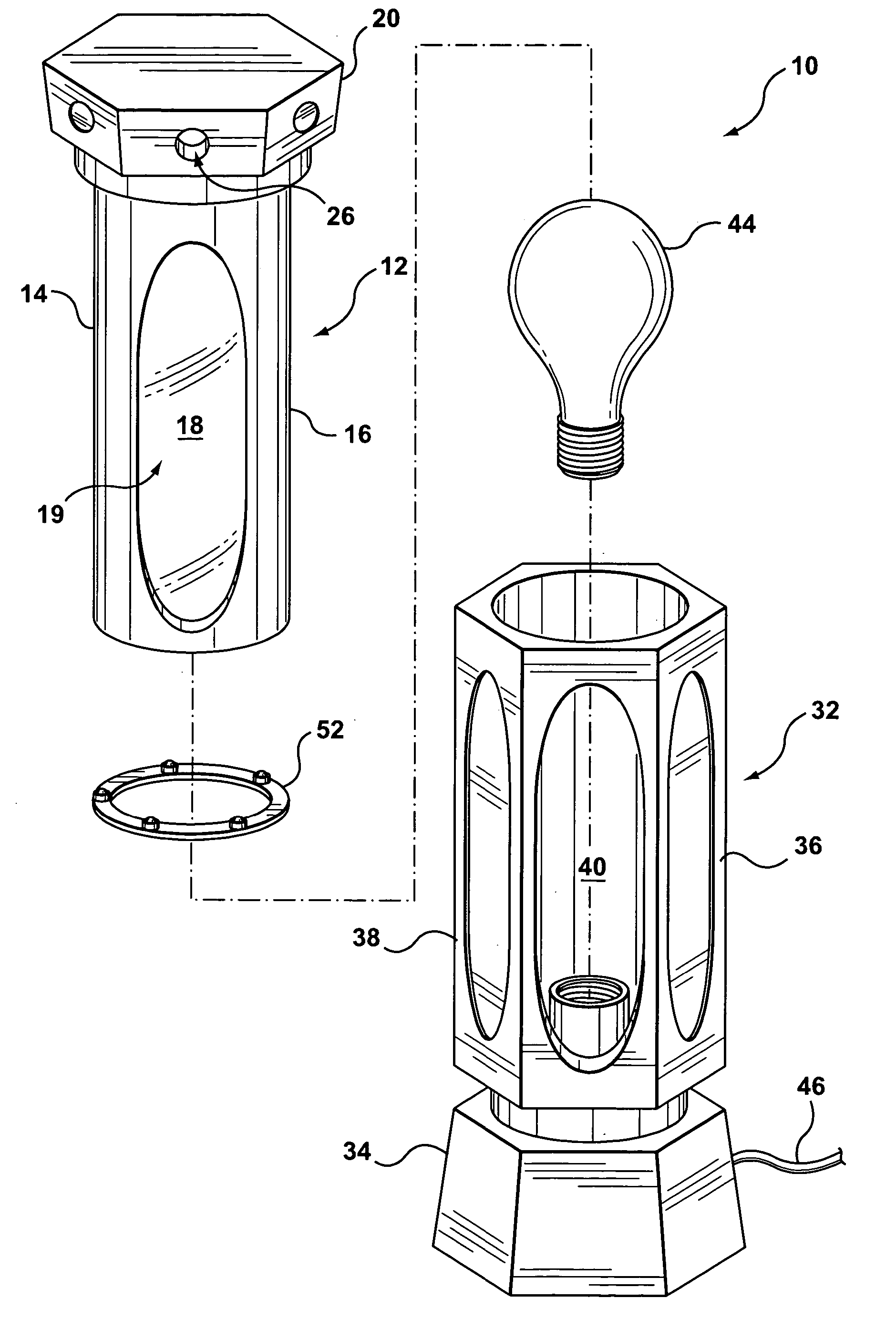
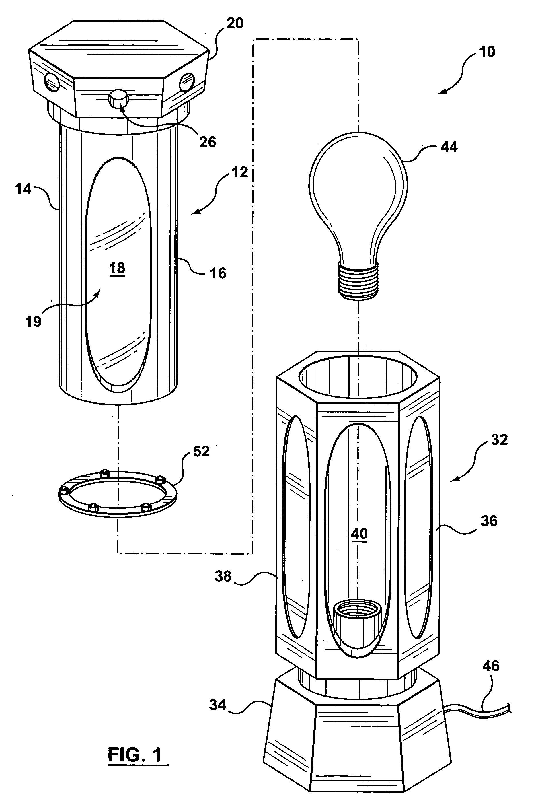
[0016] Turning to FIGS. 1 through 3, a table lamp 10 has a top unit 12 having a cylindrical tubular shroud 14 with a side wall 16 having an opening 18 therethrough. The opening is covered with a translucent light diffusing sheet 19. The lumen of the shroud is lined with a reflective sheet 21 opposite opening 18. A light trap 20 extends from the top end of the tubular shroud 14. As seen in FIGS. 2 and 3, there is an off-center heat vent hole 22 in the bottom wall 24 of the light trap inside of the cylindrical side wall 16 of tubular body 14. There is a second heat vent hole 26 in a side wall 28 of the light trap. A series of baffles 30 extend between the two heat vents so as to provide a tortuous path between the two heat vents.

[0017] A bottom u...


PUM


Abstract

A lamp has a cover at least partially enveloping a light receptacle so as to define a receptacle chamber. A light trap is provided atop the cover with a first heat vent communicating between the receptacle chamber and an interior of said light trap and a second heat vent communicating between an interior of said light trap and an ambient environment. The light trap is arranged to at least substantially prevent light which enters the first heat vent from reaching the second heat vent while allowing heat which enters said first heat vent to pass through said second heat vent. With this arrangement, the light emitted from the cover may be blocked with a shroud without overheating the lamp.

Description

CROSS-REFERENCE TO RELATED APPLICATION [0001] This application claims priority from U.S. provisional application No. 60 / 490,248, filed Jul. 28, 2003.BACKGROUND OF INVENTION [0002] This invention relates to a lamp. [0003] Sabbath observant Jews may not turn electrical switches on or off during the Sabbath: from sundown on Friday until after dark on Saturday. This can force a family to leave some lights on during this period, however, the illumination may disturb others, especially those trying to sleep. [0004] This invention seeks to ameliorate this problem. SUMMARY OF INVENTION [0005] The subject lamp reduces the inconvenience caused by a lamp that remains electrically turned on by providing a lamp suitable for reading or other purposes that is adapted to selectively provide light. [0006] The lamp has a cover at least partially enveloping a light receptacle so as to define a receptacle chamber. A light trap is provided atop the cover with a first heat vent communicating between the ...

Claims


Application Information

Patent Timeline
IPC IPC(8): F21S6/00F21V14/08F21V23/04F21V29/00F21V33/00
CPCF21S6/004F21V14/08F21V29/83F21V29/004F21V29/74F21V23/04
Inventor VEFFER, SAMUEL C.
Owner KOSHER INNOVATIONS LTD
Why Eureka
Try Eureka