
Video coding quantization

a video coding and quantization technology, applied in the field of video coding, can solve problems such as the blockiness of various types of video input, and achieve the effect of reducing the blockiness

Active Publication Date: 2005-02-17
TEXAS INSTR INC
View PDF7 Cites 12 Cited by
  • Summary
  • Abstract
  • Description
  • Claims
  • Application Information

AI Technical Summary

Benefits of technology

This has advantages including reduced blockiness arising from clipping of quantized DCT coefficients.

Problems solved by technology

However, H.263 has a problem of blockiness for various types of video input.

Method used


Image

  • Video coding quantization
  • Video coding quantization
  • Video coding quantization

Examples


Embodiment Construction

1. Overview

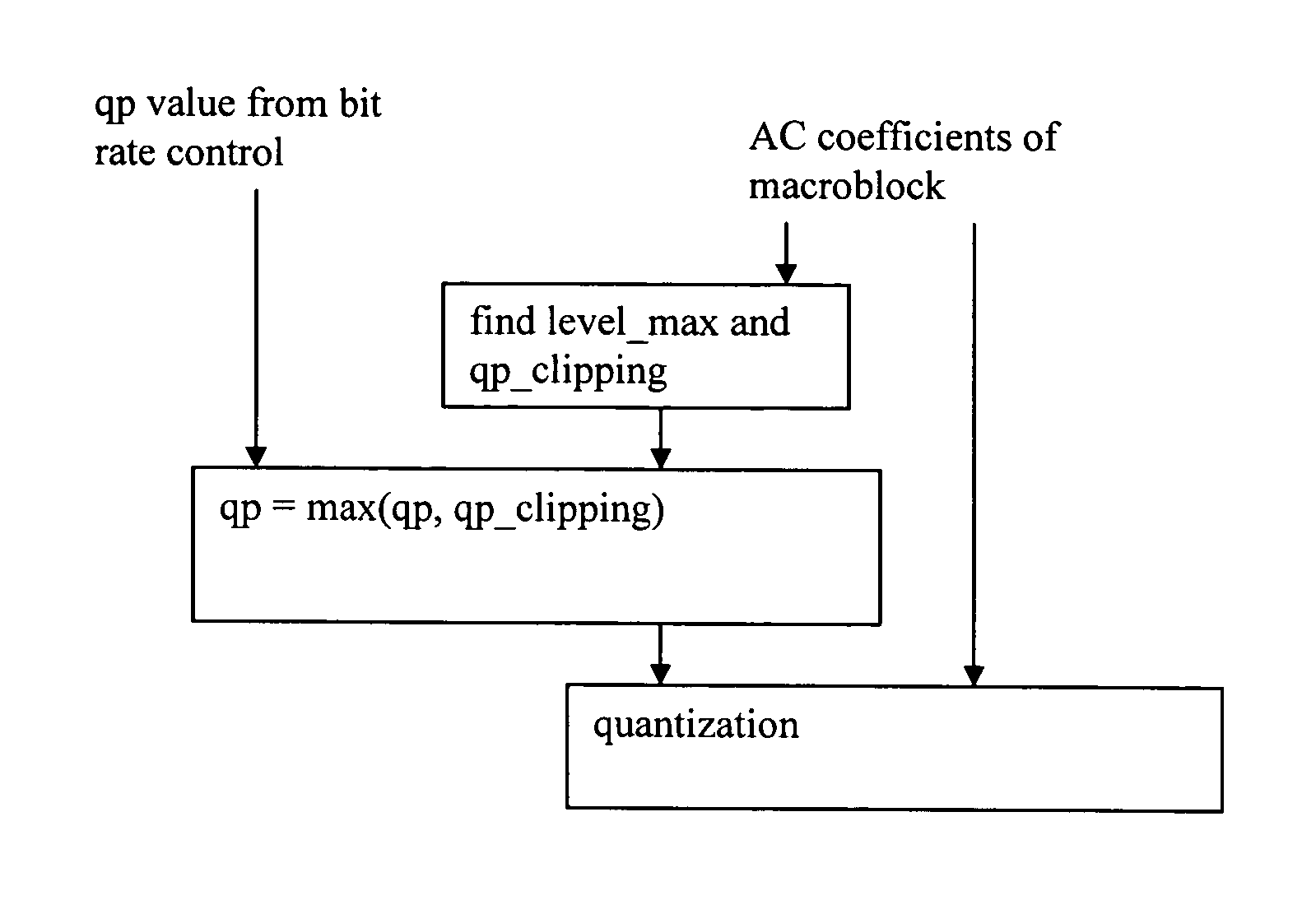
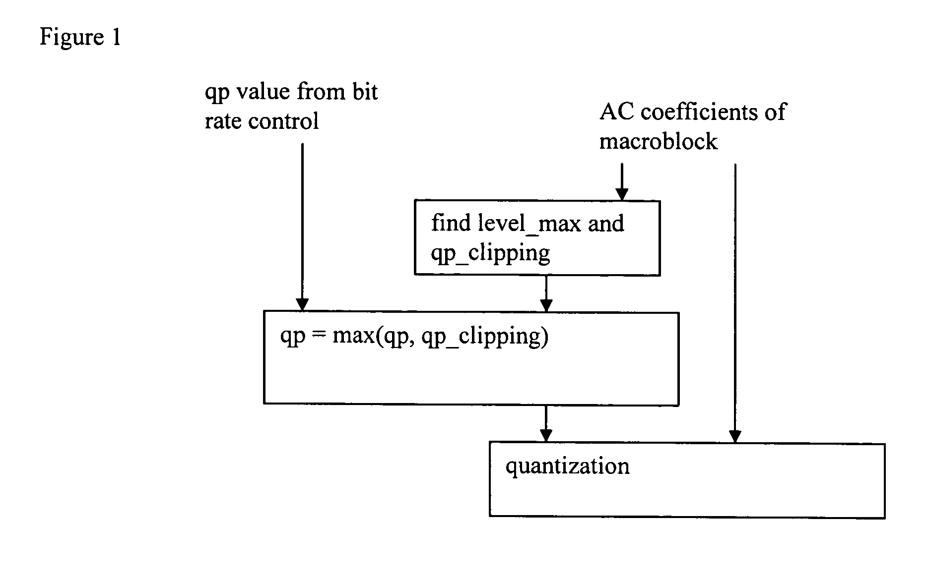
The preferred embodiment methods adapt H.263-type rate-controlled quantizer parameters by providing a minimum quantizer parameter for a block of coefficients being quantized to prevent clipping. FIG. 1 is a flow diagram. The same adaptive minimum quantizer parameter extends to other transform-type encoding which have clipping of transform coefficients to a range of values.

Preferred embodiment systems perform preferred embodiment methods with digital signal processors (DSPs) or general purpose programmable processors or application specific circuitry or systems on a chip (SoC) such as both a DSP and RISC processor on the same chip with the RISC processor controlling. In particular, digital still cameras (DSCs) with video clip capabilities could invoke the preferred embodiment methods. A stored program could be in an onboard ROM or external flash EEPROM for a DSP or programmable processor to perform the signal processing. Analog-to-digital converters and digital-to-ana...


PUM


Abstract

Modify H.263-type quantization with an adaptive quantization parameter floor; this limits clipping of quantized DCT coefficients and consequent artifacts. The maximum absolute level of AC coefficients of a DCT transformed macroblock provides a minimum quantization parameter from integer division by 256 when the quantized levels are clipped to a range such as −127 to +127.

Description

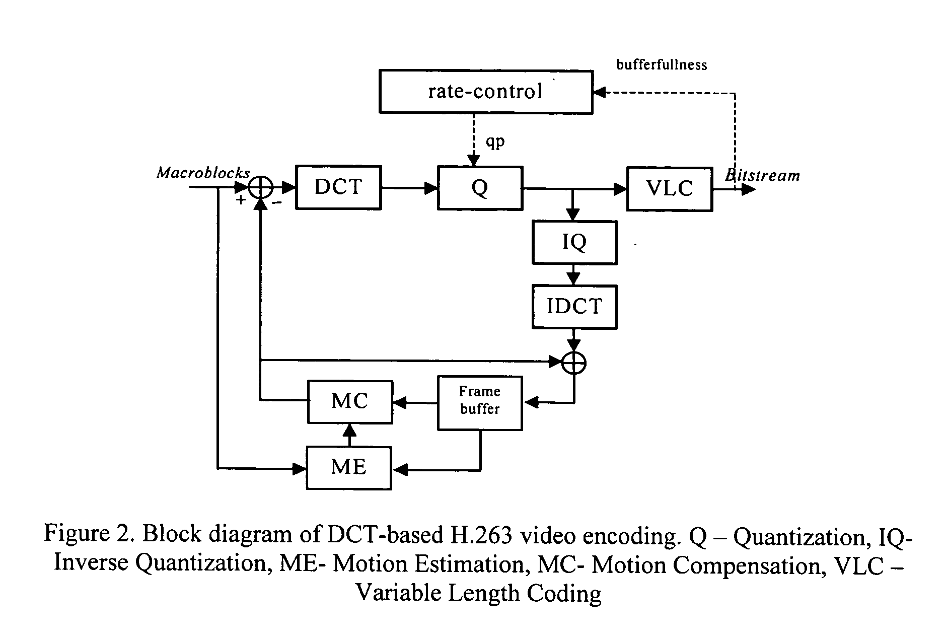
BACKGROUND The present invention relates to video coding, and more particularly to block-based video coding such as H.263. Various applications for digital video communication and storage exist, and corresponding international standards have been and are continuing to be developed. Low bit rate communications, such as, video telephony and conferencing, led to the H.261 standard with bit rates as multiples of 64 kbps. Demand for even lower bit rates resulted in the H.263 standard. As with other DCT-based video compression standards (H.261, MPEG1, MPEG2, MPEG4), H.263 decomposes a picture into a macroblocks where each macroblock contains four 8×8 luminance blocks plus two 8×8 chrominance blocks. With input 8-bit integer pixel values, conversion to luminance and chrominance pixel values in the range −256 to +255 (i.e., 9 bits). FIG. 2 depicts the functional blocks of DCT-based video encoding. In order to reduce the bit-rate, 8×8 DCT is used to convert the 8×8 blocks (luminance and c...

Claims


Application Information

Patent Timeline
Patent Type & Authority Applications(United States)
IPC IPC(8): H04N7/12H04N7/26
CPCH04N19/176H04N19/136H04N19/124
Inventor ZHOU, MINHUA
Owner TEXAS INSTR INC
Learn More