Construction machine

Active Publication Date: 2005-02-17
KOMATSU LTD
View PDF5 Cites 128 Cited by
  • Summary
  • Abstract
  • Description
  • Claims
  • Application Information

AI Technical Summary

Benefits of technology

[0023] With the construction machine of claim 4, energy regeneration operation of claims 1 to 3 can be performed smoothly and reliably.
[0024] With the construction machine of claim 5, the rotational speed of the electrical power ge

Problems solved by technology

That is, in the hydraulic shovel in which an engine having an output corresponding to a maximum required horsepower is mounted, the output that the engine can output has not been employed effectively.
However, in attempting to reliably collect all energy described

Method used


Image

  • Construction machine
  • Construction machine
  • Construction machine

Examples


Embodiment Construction

[0035] Next, specific embodiments of a construction machine of the present invention will be described in detail with reference to the drawings.

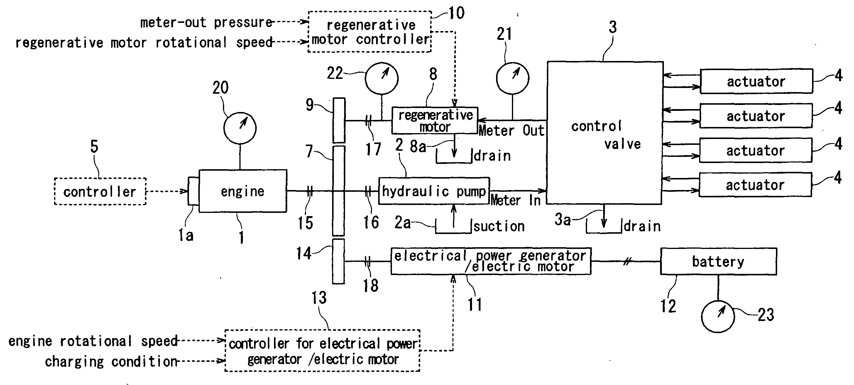
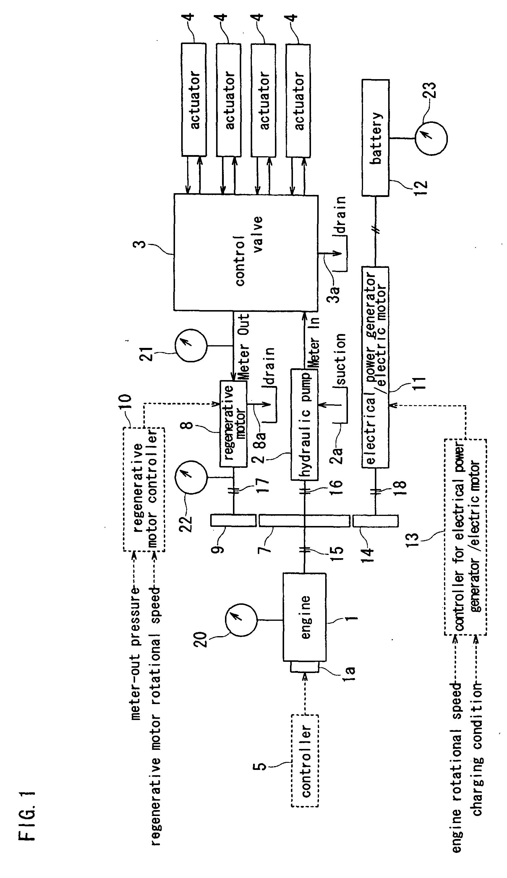
[0036]FIG. 1 is a schematic block diagram for explaining a drive system of a construction machine in one embodiment of the present invention. In FIG. 1, the reference numeral 1 denotes an engine, and the rotational speed of this engine 1 is regulated by a governor 1a receiving a governor command from a controller 5. A rotation sensor 20 for detecting the engine rotational speed is provided on the engine 1. Furthermore, the reference numeral 2 denotes a variable capacity type hydraulic pump which is driven by the engine 1, and pressure oil (mater-in) which is discharged from the hydraulic pump 2 is supplied to various actuators 4, 4, for example, a boom cylinder, an arm cylinder, a bucket cylinder, a right side travel motor, a left side travel motor, a swing motor, and the like via a control valve 3. At this time, the angle of inclination of...


PUM


Abstract

In order to provide a construction machine by which energy regeneration can be performed reliably and battery and electrical power generator can be miniaturized, a construction machine has an engine, a hydraulic pump driven by the engine, and an actuator driven by discharge oil from the hydraulic pump, and a regenerative motor which rotates by return oil from the actuator is connected to the rotation shaft of the hydraulic pump. The hydraulic pump is driven by the engine and the regenerative motor when drive torque necessary in the hydraulic pump is larger than output torque generated by operation of the regenerative motor. Meanwhile, the hydraulic pump is driven by the regenerative motor when the drive torque of the hydraulic pump is smaller than output torque of the regenerative motor, and an electrical power generator connected to the rotation shaft of the hydraulic pump is operated to generate electricity by excess torque which has not been energy-regenerated in the hydraulic pump so that this generated electrical power is charged in a battery.

Description

BACKGROUND OF THE INVENTION [0001] 1. Field of the Invention [0002] The present invention relates to a construction machine such as a hydraulic shovel and the like. [0003] 2. Description of the Background Art [0004] Regarding a conventional construction machine, its mainstream is a-hydraulically-operated system. For example, in a hydraulic shovel, driving of a farm working machinery, revolution of an upper revolving body, and traveling of a lower traveling body are performed by a hydraulic actuator (hydraulic cylinder, hydraulic motor). Operations are executed by controlling the pressure oil which is discharged from a hydraulic pump whose drive source is an engine and which is supplied to that hydraulic actuator. [0005] Operations of the hydraulic shovel are not always operations which need 100% power with respect to the engine capacity but are operations which need for example only 90% or 80% power in many cases. That is, as shown in FIG. 8 which is an engine-torque characteristic ...

Claims


Application Information

Patent Timeline
IPC IPC(8): E02F9/20E02F9/22F02D29/00F02D29/04F04B17/00F04B17/05F04B49/00F15B21/14
CPCE02F9/2025E02F9/2075E02F9/2217E02F9/2235F04B2203/0603F04B17/00F04B17/05F04B49/00F04B2201/1202E02F9/2246E02F9/20
Inventor OGURI, HIDEO
Owner KOMATSU LTD
Why Eureka
Try Eureka