Hybrid drive apparatus

a hybrid drive and drive shaft technology, applied in mechanical devices, transportation and packaging, gearing, etc., can solve the problems of large differential rotation (slipping velocity) of friction materials, inability to eliminate drag torque, and inability to efficiently perform energy regeneration by the motor generator, so as to improve power transmission efficiency and energy efficient regeneration

Inactive Publication Date: 2013-02-07
HONDA MOTOR CO LTD
View PDF0 Cites 17 Cited by
  • Summary
  • Abstract
  • Description
  • Claims
  • Application Information

AI Technical Summary

Benefits of technology

[0022]According to the invention, it is possible to provide a hybrid drive apparatus that enables efficient energy regeneration by the motor generator by separating the power transmission path through which the driving force from the engine is transmitted, from the power transmission path between the motor generator and the drive wheels when decelerating regeneration is performed by the motor generator during deceleration of the vehicle, and also makes it possible to set a variety of driving modes while improving power transmission efficiency.

Problems solved by technology

Therefore, when performing decelerating regeneration by the motor generator during deceleration of the vehicle, the power transmission path through which the driving force from the engine is transmitted cannot be separated from the power transmission path between the motor generator and drive wheels, and it is not possible to eliminate drag torque until the engine stops.
As a result, it is not possible to perform efficient energy regeneration by the motor generator.
However, in the planetary gear mechanism of the hybrid drive apparatus configured as mentioned above, comparatively large relative velocity (differential rotation) between the sun gear and the ring gear causes large differential rotation (slipping velocity) of the friction material when the clutch is disengaged.
Therefore, friction loss in the clutch affects the transmission efficiency of the hybrid drive apparatus.

Method used


Image

  • Hybrid drive apparatus
  • Hybrid drive apparatus
  • Hybrid drive apparatus

Examples


first embodiment

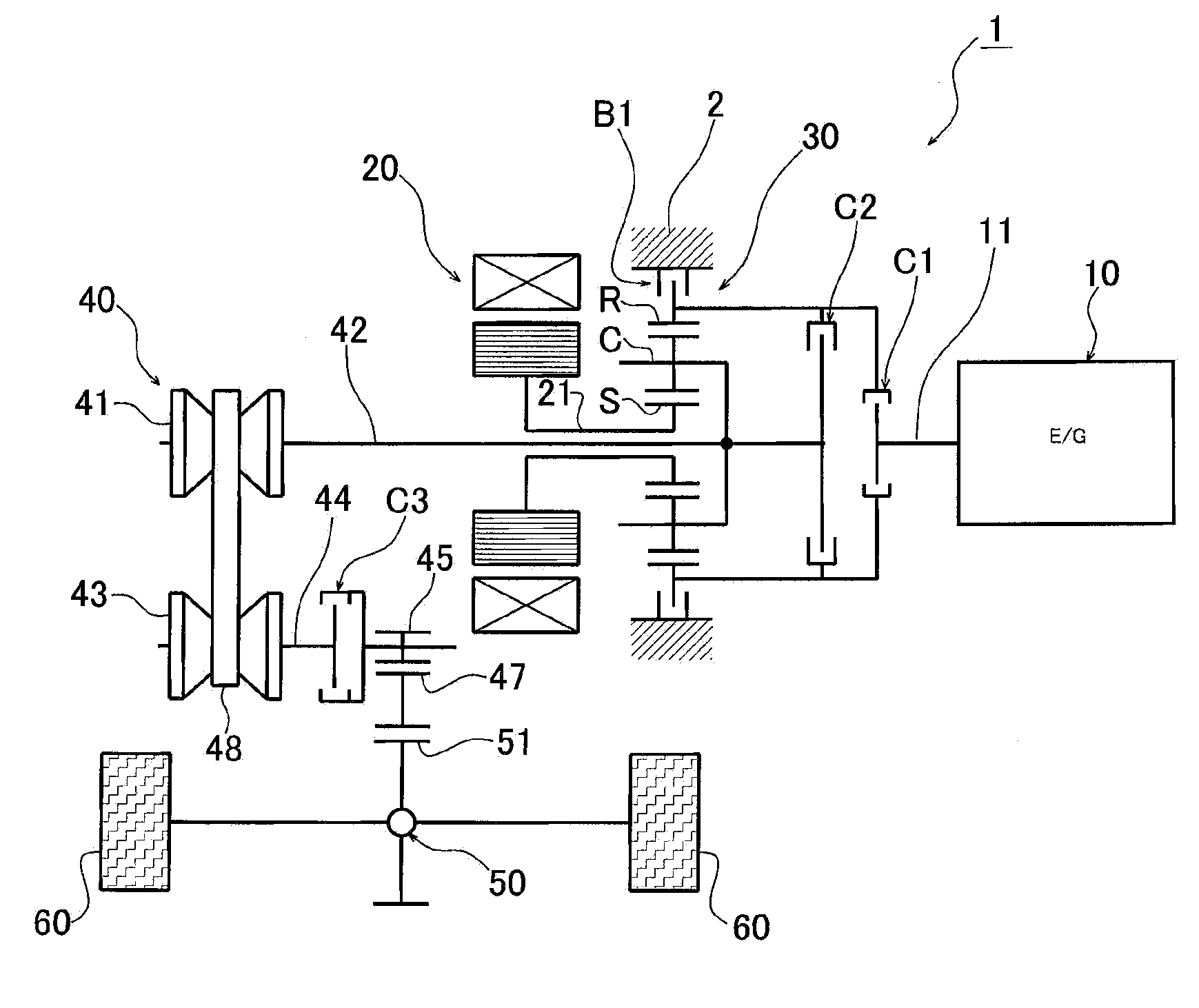
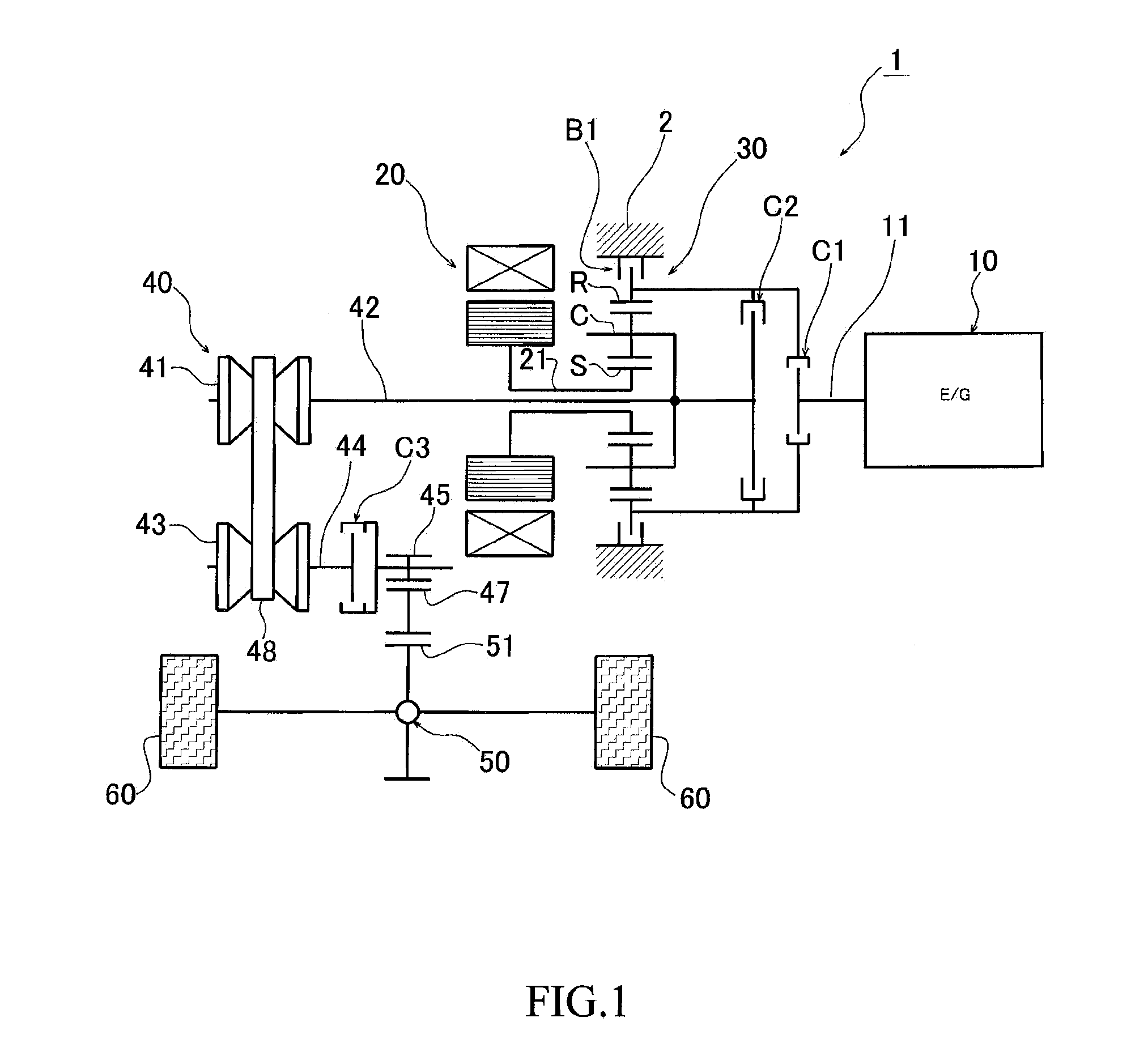
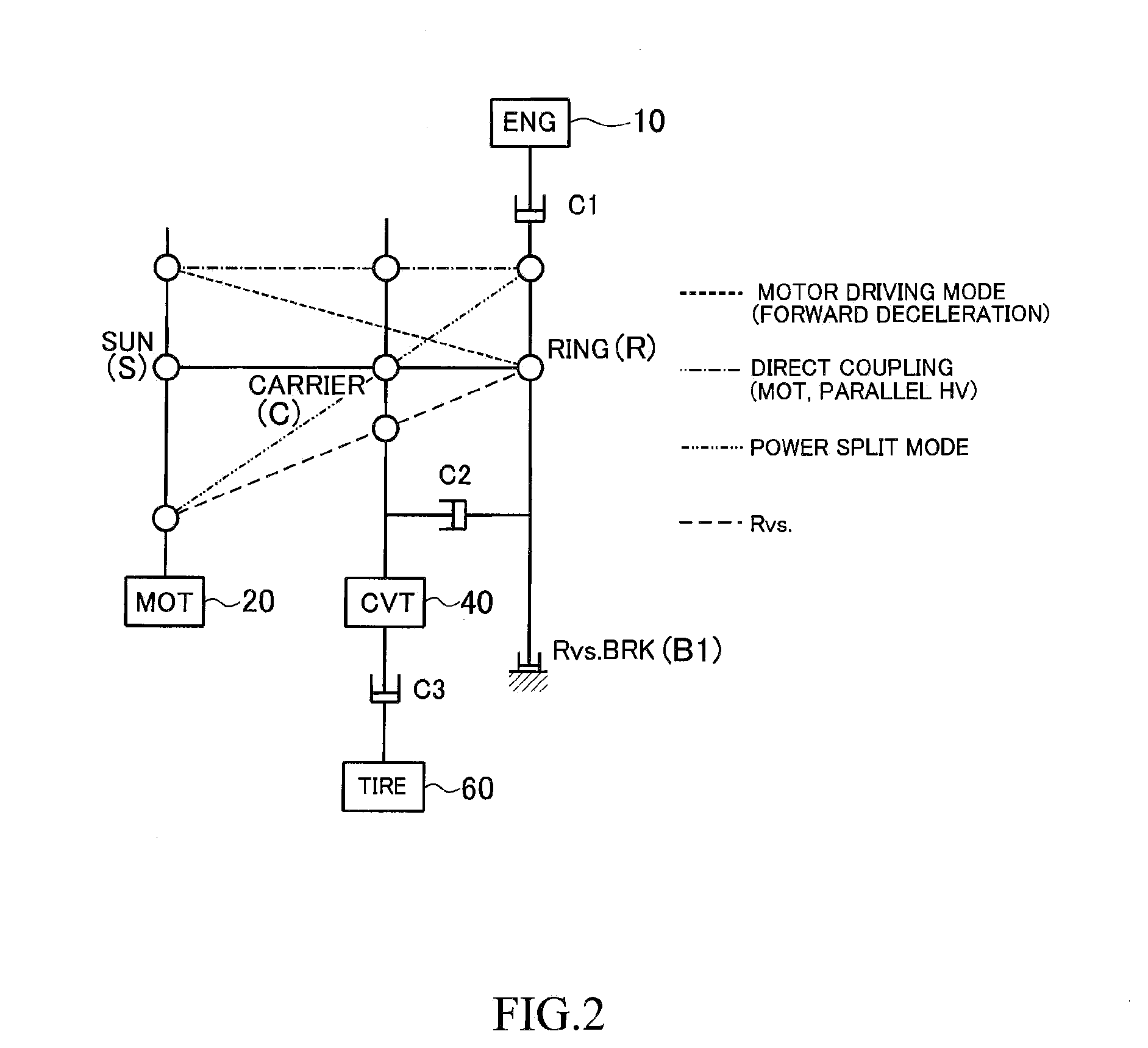
[0030]FIG. 1 is a skeleton diagram illustrating the configuration of a hybrid drive apparatus according to a first embodiment of the invention. Also, FIG. 2 is a nomographic diagram (velocity diagram) illustrating the velocity relationship among various elements of a planetary gear mechanism provided in the hybrid drive apparatus. A hybrid drive apparatus 1 illustrated in FIG. 1 includes an engine 10 that generates power by combustion of fuel, a motor generator 20 that functions as an electric motor and a generator, a single pinion-type planetary gear mechanism 30 having three elements, i.e., a sun gear S, a ring gear R, and a carrier C, and a belt-type continuously variable transmission mechanism 40 having a belt 48 that is run between a driving pulley 41 and a driven pulley 43.

[0031]An output shaft (rotating shaft) 21 of the motor generator 20 is coupled to the sun gear S of the planetary gear mechanism 30. An input shaft (first rotating shaft) 42 of the continuously variable tran...

second embodiment

[0052]Next, a second embodiment of the invention is described. In the description of the second embodiment and the corresponding drawings, component parts that are identical or equivalent to those in the first embodiment are denoted by the same symbols, and a detailed description of those parts is omitted. Also, matters other than those described below are the same as those in the first embodiment.

[0053]FIG. 5 is a skeleton diagram illustrating the configuration of a hybrid drive apparatus 1-2 according to the second embodiment of the invention. The hybrid drive apparatus 1-2 illustrated in FIG. 5 includes, instead of the second clutch C2 provided between the ring gear R and carrier C of the planetary gear mechanism 30 (between the output shaft 11 of the engine 10 and the input shaft 42 of the continuously variable transmission mechanism 40) in the hybrid drive apparatus 1 according to the first embodiment illustrated in FIG. 1, another clutch C2′ that is provided between the sun ge...

third embodiment

[0055]Next, a third embodiment of the invention is described. FIG. 6 is a skeleton diagram illustrating the configuration of a hybrid drive apparatus according to the third embodiment of the invention. A hybrid drive apparatus 1-3 according to the third embodiment illustrated in FIG. 6 includes, instead of the third clutch C3 provided on the output shaft (second rotating shaft) 44 of the continuously variable transmission mechanism 40 which connects to the driven pulley 43 in the hybrid drive apparatus 1 according to the first embodiment illustrated in FIG. 1, another third clutch C3′ that is provided on the input shaft (first rotating shaft) 42 of the continuously variable transmission mechanism 40 which connects to the driving pulley 41. The configuration of this hybrid drive apparatus is otherwise the same as that of the hybrid drive apparatus 1 according to the first embodiment.

[0056]In the hybrid drive apparatus 1-3 according to this embodiment, the third clutch C3′ is provided...


PUM


Abstract

In a hybrid drive apparatus having an engine, a motor generator, and a planetary gear mechanism in which the output shaft of the motor generator is coupled to a sun gear, the output shaft of the engine is coupled to a ring gear, and the input shaft of a continuously variable transmission mechanism is coupled to a carrier, the hybrid drive apparatus includes a first clutch that can switch engagement/disengagement between the output shaft of the engine and the ring gear, a second clutch that can switch engagement/disengagement between the carrier and the ring gear, and a third clutch that can switch engagement/disengagement on the input shaft of the transmission mechanism. Consequently, the power transmission path for the driving force from the engine can be separated from the power transmission path between the motor generator and drive wheels, and various driving modes can be set while improving power transmission efficiency.

Description

CROSS REFERENCE TO RELATED APPLICATION[0001]The present disclosure contains subject matter related to Japanese Patent Application No. 2011-169679 filed on Aug. 2, 2011, the entire contents of which are incorporated herein by reference.BACKGROUND OF THE INVENTION[0002]1. Field of the Invention[0003]The present invention relates to a hybrid drive apparatus including an engine that generates power by combustion of fuel, and a motor generator that functions as an electric motor and a generator.[0004]2. Description of Related Art[0005]In the related art, as set forth in, for example, Japanese Patent No. 3414059 (Patent Document 1) and Japanese Patent No. 3458795 (Patent Document 2), there are hybrid drive apparatuses for a vehicle which include an engine that generates power by combustion of fuel, a motor generator that functions as an electric motor and a generator, a planetary gear mechanism that is capable of combining and outputting driving forces input from the engine and the motor ...

Claims


Application Information

Patent Timeline
Patent Type & Authority Applications(United States)
IPC IPC(8): F16H3/72F16H9/04
CPCB60K6/365Y02T10/6239B60K6/445Y02T10/62
Inventor YAGASAKI, TORU
Owner HONDA MOTOR CO LTD
Why Eureka
Try Eureka