Method and apparatus for controlling friction between a fluid and a body

a technology of fluid and body, applied in the direction of underwater equipment, special-purpose vessels, vessel construction, etc., can solve the problems of high friction between the device or structure and the fluid, underwater vehicles such as submarines or torpedoes, and experience a high level of friction, so as to reduce the friction between the fluid and the body, reduce the detrimental drag effect of friction, and reduce the effect of friction

Inactive Publication Date: 2005-02-24
WSOU INVESTMENTS LLC +1
View PDF19 Cites 49 Cited by
  • Summary
  • Abstract
  • Description
  • Claims
  • Application Information

AI Technical Summary

Benefits of technology

While prior attempts to reduce friction between a fluid and a surface moving through that fluid were effective in many regards, we have realized that it would be advantageous to further reduce this friction. Such a reduction would have the effect of minimizing the detrimental drag effects of friction and would decrease the drag on underwater vehicles thus increasing the maximum speed and reducing the noise generated by those vehicles. Since less power is required to propel a vehicle experiencing lower friction, we have also recognized that fuel requirements would be reduced.

Problems solved by technology

In many cases, friction between the device or structure and the fluid is of paramount concern.
For example, underwater vehicles (such as submarines or torpedoes), which are capable of maneuvering partially or entirely under water, experience a high level of friction due to the contact between the water and the surface of the vehicle.
Since water is very dense, such vehicles experience significant friction.
The drag forces caused by friction reduce the maximum speed at which the vehicle can travel and increase the amount of noise generated by the movement of the vehicles—both of which may be undesirable.

Method used


Image

  • Method and apparatus for controlling friction between a fluid and a body
  • Method and apparatus for controlling friction between a fluid and a body
  • Method and apparatus for controlling friction between a fluid and a body

Examples


Embodiment Construction

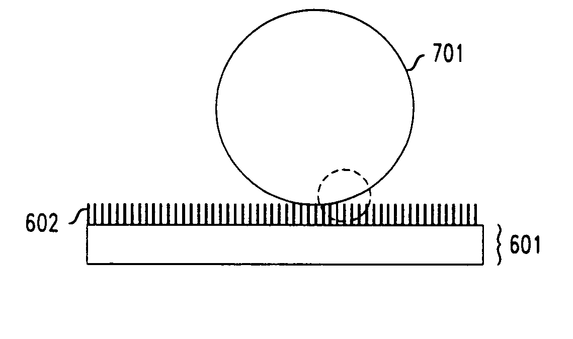
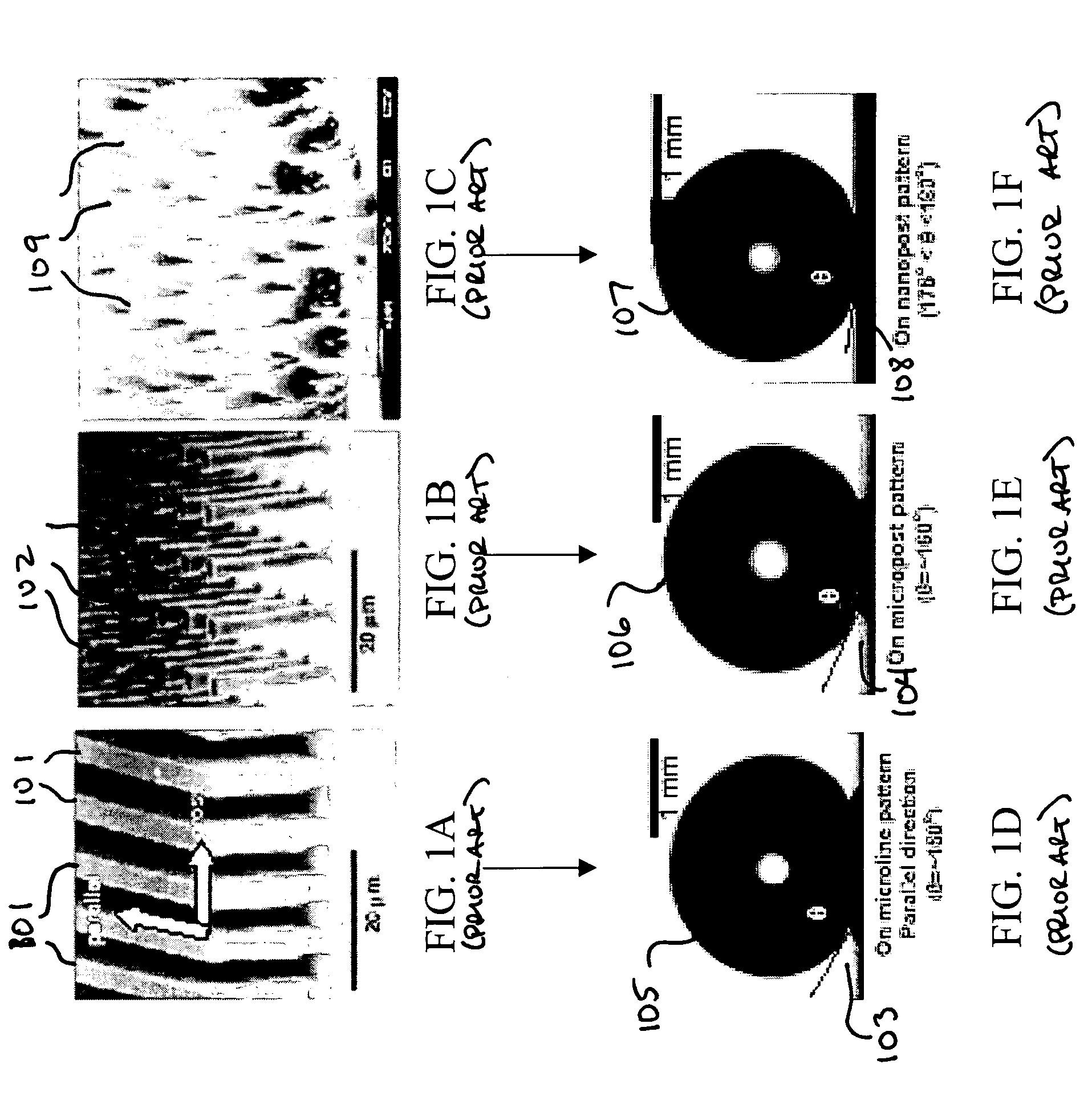
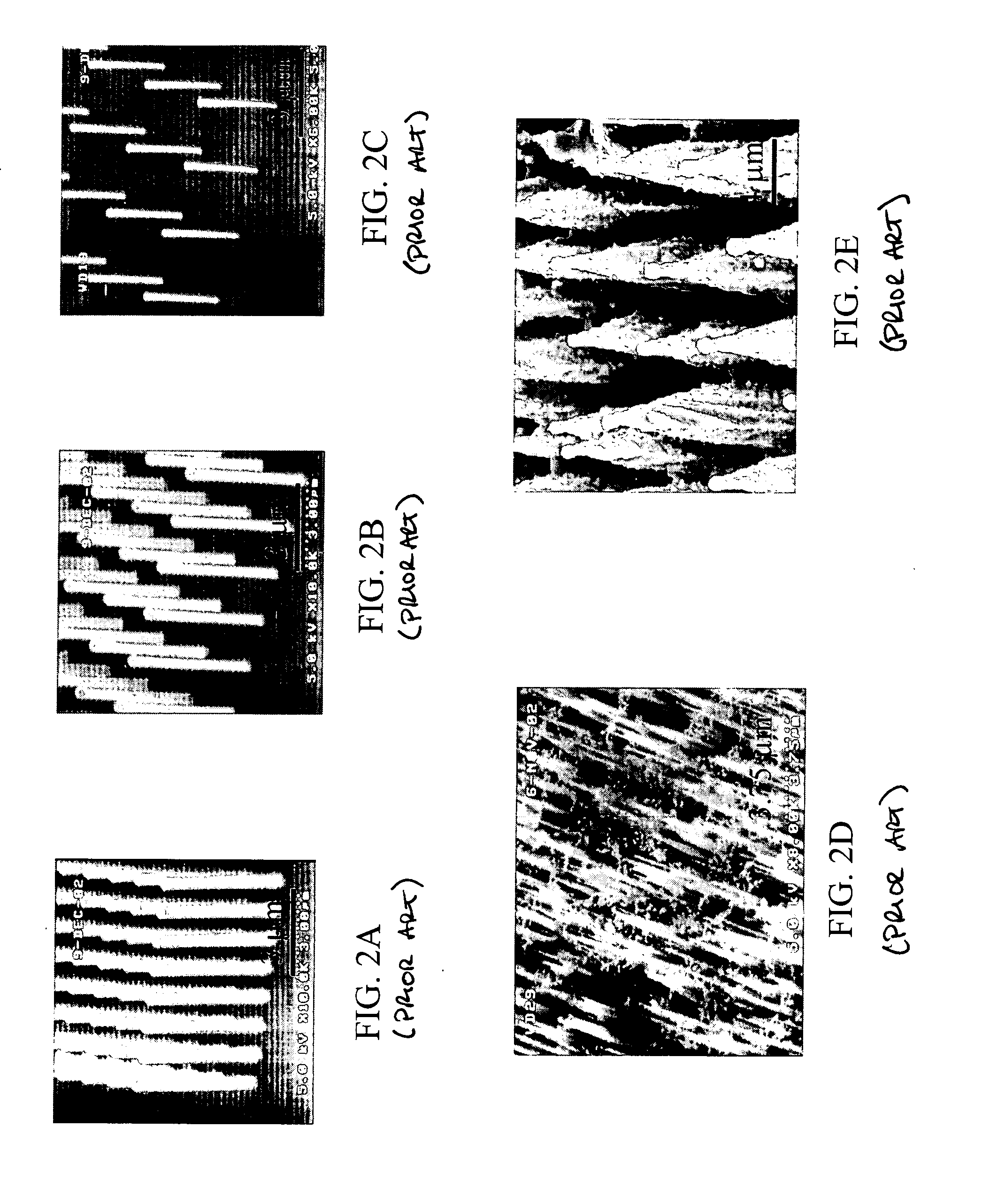
Reducing the friction between a fluid and a body moving through that fluid is highly desirable in many situations. We have realized that such reductions may be achieved by using nanostructured or microstructured surfaces on such bodies. To date, nanostructures and / or microstructures have primarily been used in microfluidics applications (for example, small amounts of fluid disposed, illustratively, in a channel) to reduce the flow resistance exerted on the droplet. These applications are useful in understanding how nanostructures or microstructures can be used to reduce flow resistance of a liquid in contact with the surface. One such application is described in “Nanostructured Surfaces for Dramatic Reduction of Flow Resistance in Droplet-based Microfluidics”, J. Kim and C. J. Kim, IEEE Conf. MEMS, Las Vegas, Nev., January 2002, pp. 479-482, which is hereby incorporated by reference herein in its entirety. The Kim reference teaches that, by finely patterning the surface in contact ...


PUM


Abstract

A method and apparatus is disclosed wherein nanostructures or microstructures are disposed on a surface of a body (such as a submersible vehicle) that is adapted to move through a fluid, such as water. The nanostructures or microstructures are disposed on the surface in a way such that the contact between the surface and the fluid is reduced and, correspondingly, the friction between the surface and the fluid is reduced. In an illustrative embodiment, the surface is a surface on a submarine or other submersible vehicle (such as a torpedo). Illustratively, electrowetting principles are used to cause the fluid to at least partially penetrate the nanostructures or microstructures on the surface of the body in order to selectively create greater friction in a desired location of the surface. Such penetration may be used, for example, to create drag that alters the direction or speed of travel of the body.

Description

FIELD OF THE INVENTION The present invention relates generally to reducing friction on moving bodies and, more particularly, controlling such friction by using extremely small, predetermined surface features disposed on the surface of the body. BACKGROUND OF THE INVENTION Many beneficial devices or structures in myriad applications are characterized at least in part by having a surface that moves through or is in contact with at least one fluid. In many cases, friction between the device or structure and the fluid is of paramount concern. For example, underwater vehicles (such as submarines or torpedoes), which are capable of maneuvering partially or entirely under water, experience a high level of friction due to the contact between the water and the surface of the vehicle. Since water is very dense, such vehicles experience significant friction. The drag forces caused by friction reduce the maximum speed at which the vehicle can travel and increase the amount of noise generated ...

Claims


Application Information

Patent Timeline
Patent Type & Authority Applications(United States)
IPC IPC(8): B63B1/36B63G8/20B63H25/50B63H25/52F15D1/12
CPCB63B1/36B63G8/20Y02T70/121B63H25/52F15D1/10B63H25/50Y02T70/10
Inventor KORNBLIT, AVINOAMKROUPENKINE, TIMOFEI NIKITAMANDICH, MARY LOUISESCHNEIDER, TOBIAS MANUELTAYLOR, JOSEPH ASHLEYWEISS, DONALDYANG, SHU
Owner WSOU INVESTMENTS LLC
Why Eureka
Try Eureka