
Method and apparatus for processing edge surfaces of optical fibers, and method and apparatus for fusion splicing optical fibers

a technology of optical fibers and edge surfaces, applied in the field of optical fiber edge surface processing, to achieve the effect of reducing the loss of spli

Inactive Publication Date: 2005-02-24
FUJITSU LTD
View PDF8 Cites 9 Cited by
  • Summary
  • Abstract
  • Description
  • Claims
  • Application Information

AI Technical Summary

Benefits of technology

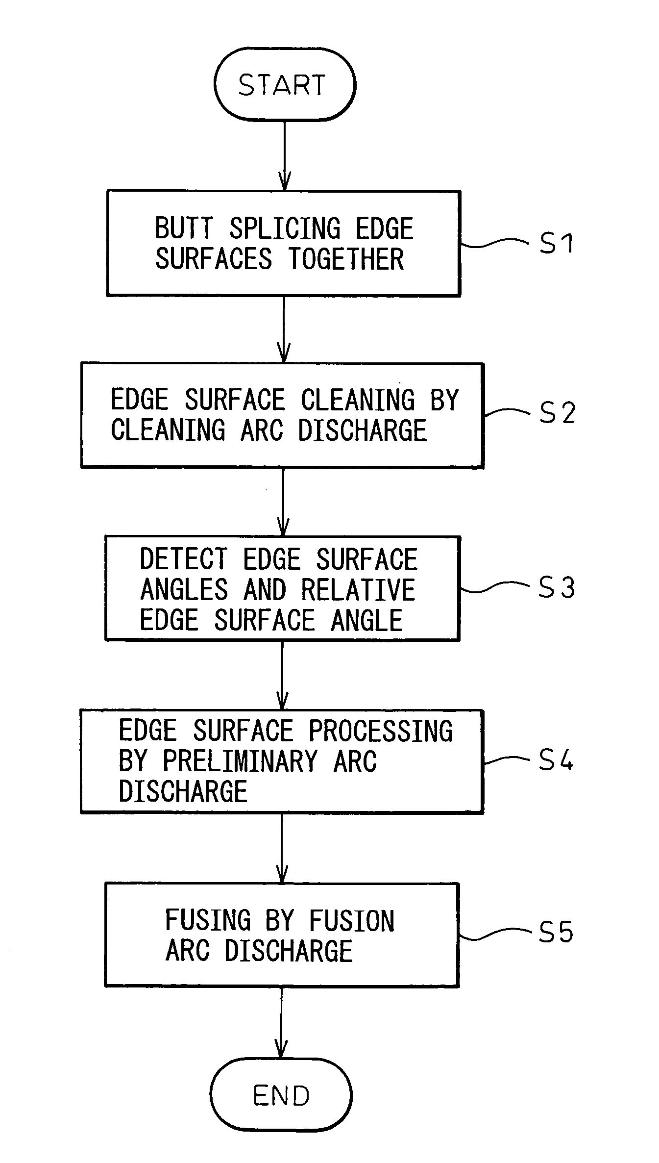
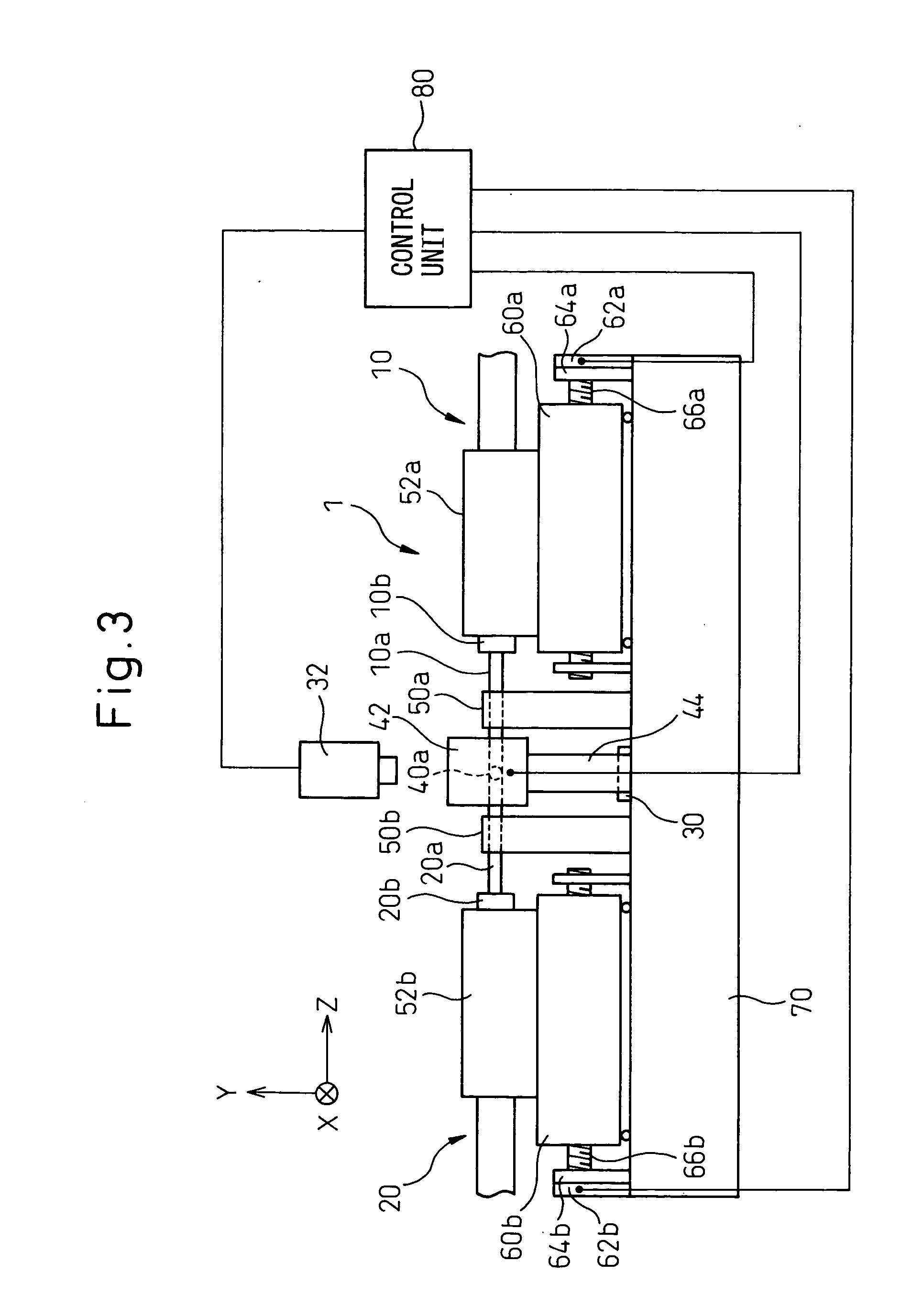
[0008] An object of the present invention is to provide a method and apparatus for processing the edge surfaces of optical fibers, wherein even when the edge surface angle of each of the two fibers to be spliced together, or their relative edge surface angle, has a large value, splice loss can be reduced in a simple manner by melting and shaping the splicing edge surfaces without suspending the splicing operation; another object of the invention is to provide an optical fiber fusion splicing method and apparatus for fusion splicing the optical fibers in a short time, after the above processing has been performed.

Problems solved by technology

At this time, there can occur cases where the cut face is not perpendicular to the fiber axis because of the lack of skill of the operator or an adjustment error of the optical fiber cutter.

Method used


Image

  • Method and apparatus for processing edge surfaces of optical fibers, and method and apparatus for fusion splicing optical fibers
  • Method and apparatus for processing edge surfaces of optical fibers, and method and apparatus for fusion splicing optical fibers
  • Method and apparatus for processing edge surfaces of optical fibers, and method and apparatus for fusion splicing optical fibers

Examples


Embodiment Construction

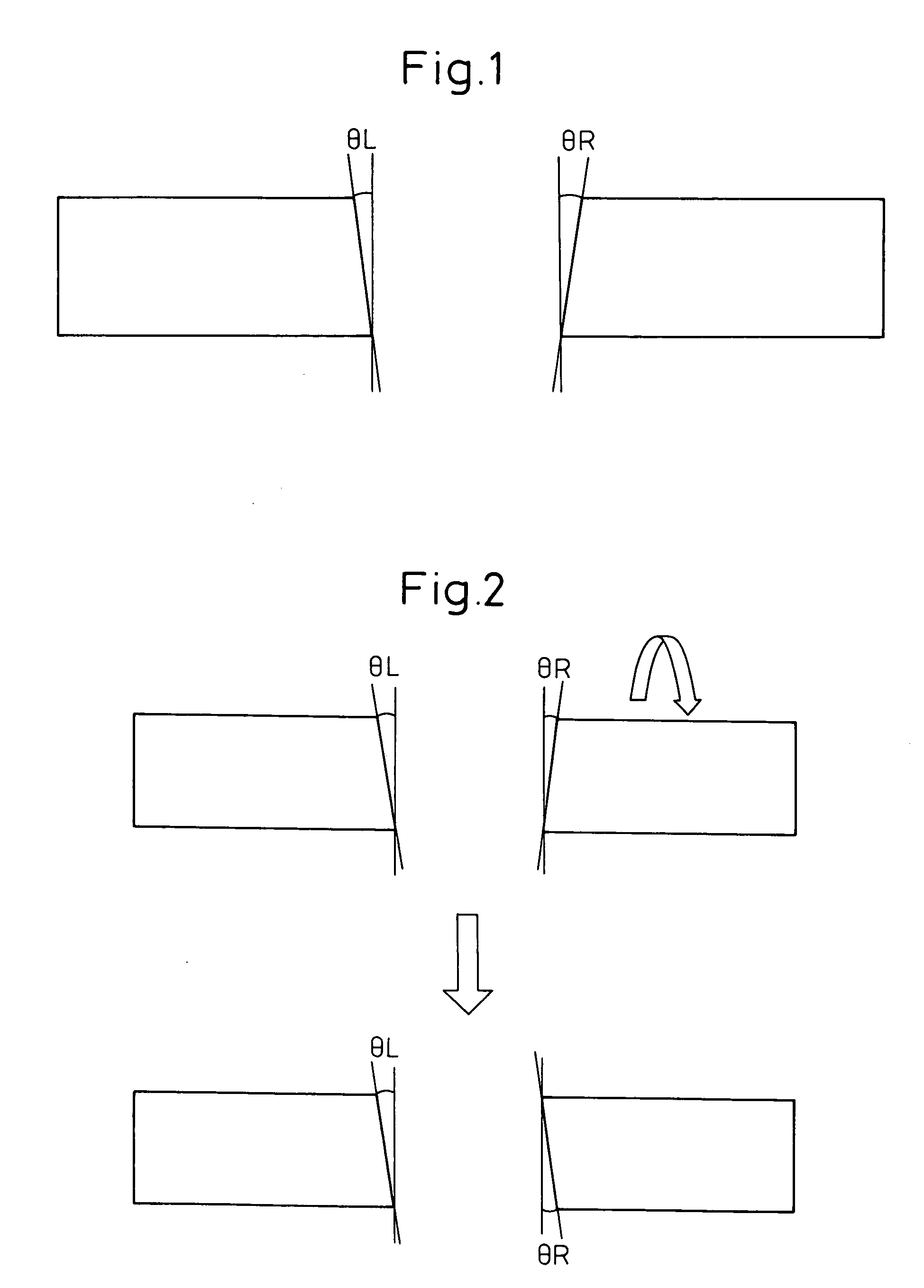
[0039] Before describing the embodiments of a method and apparatus for processing the edge surfaces of optical fibers and a method and apparatus for fusion splicing the optical fibers according to the present invention, the prior art and its associated problems will be described with reference to FIGS. 1 and 2.

[0040] Conventionally, in a process preparatory to fusion splicing two optical fibers, the end face of each fiber is cut and processed to even off the splicing edge surface of the fiber. At this time, there can occur cases where the cut face is not perpendicular to the fiber axis because of the lack of skill of the operator or an adjustment error of the optical fiber cutter.

[0041]FIG. 1 shows edge surface angles θL and θR, each representing the angle that the cut face of a fiber makes with the fiber axis. If, in this condition, the two optical fibers are pushed in and fused together by an arc discharge, there occurs the problem that good splicing performance with low splice ...


PUM


Abstract

An optical fiber edge surface processing method has the steps of capturing a transmitted-light image of end portions of two optical fibers placed facing each other, and extracting, based on a brightness distribution in the transmitted-light image, edge surface information of each of the two optical fibers to be spliced together; selecting a discharge condition corresponding to the edge surface information from among a plurality of discharge conditions prestored in a storage unit; and melting the splicing edge surfaces of the two optical fibers in accordance with the selected discharge condition, and thereby shaping the splicing edge surfaces. With this method, splice loss can be reduced in a simple manner, even when the edge surface angle of each optical fiber, or the relative edge surface angle between the two optical fibers, or the amount of chipping at the splicing cross section of each optical fiber, is large.

Description

CROSS REFERENCE TO RELATED APPLICATION [0001] This application is based upon and claims the benefit of priority from the prior Japanese Patent Application No. 2003-196704, filed on Jul. 14, 2003, the entire contents of which are incorporated herein by reference. BACKGROUND OF THE INVENTION [0002] 1. Field of the Invention [0003] The present invention relates to a method and apparatus for processing the edge surfaces of optical fibers, and also relates to a method and apparatus for fusion splicing optical fibers. More particularly, the invention relates to a method and apparatus for processing the edge surfaces of optical fibers, wherein in a process of fusion splicing two optical fibers, an arc discharge having the amount of discharge energy adjusted to match the condition of the edge surface of each fiber is applied to the splicing edge surface of the fiber to melt and shape the splicing edge surface, thereby reducing splice loss attributable to the edge surface condition; the inve...

Claims


Application Information

Patent Timeline
IPC IPC(8): G02B6/255
CPCG02B6/2551
Inventor SAITO, SHIGERUKAWANISHI, NORIYUKIKANAI, YOSHINORITERAUCHI, HIDEAKISAITO, OSAMUISHIJIMA, SHIZUO
Owner FUJITSU LTD
Learn More