Method of splicing two optical fibers

a technology of optical fibers and splicing methods, which is applied in the direction of optics, instruments, optical light guides, etc., can solve the problems of increasing the risk of fracture of optical fibers or increasing the loss of light propagating in optical fibers, and the mechanical strength of the fusion-spliced portion is lower than that of the other portions of optical fibers

Inactive Publication Date: 2003-04-22
SUMITOMO ELECTRIC IND LTD
View PDF6 Cites 20 Cited by
  • Summary
  • Abstract
  • Description
  • Claims
  • Application Information

AI Technical Summary

Benefits of technology

Even in the case of two optical fibers of mutually different mode field diameters being spliced each other by fusion splice, the splice loss can be reduced based on decrease in the difference between the mode field diameters, by diffusing the additive by the heating treatment at the first temperature in the additive-diffusing step. The thermal strain appears near the fusion-spliced portion in the fusion step and in the additive-diffusing step, but this thermal strain is removed in the thermal-strain-removing step of heating the wider region than the heated regions in the fusion step and in the additive-diffusing step of the fusion-spliced portion, at the second temperature being not less than 500.degree. C. nor more than 1200.degree. C. and being lower than the first temperature, whereby the sufficient mechanical strength is ensured in and around the fusion-spliced portion of optical fiber apparatus. Here the "heated region" stated in the present invention means a region in which the temperature becomes 500.degree. C. and higher during heating of the optical fibers. The removed state of thermal strain is also maintained during the cooling after the thermal-strain-removing step, so that the satisfactory mechanical strength is ensured in and around the fusion-spliced portion of optical fiber apparatus. The cooling rate is preferably not more than 4000.degree. C. / min.
The fabrication method of optical fiber apparatus according to the present invention is characterized in that in the thermal-strain-removing step the heating treatment is carried out by arc discharge, by flame generated with supply of inflammable gas and oxygen gas to a burner, or by a heater. In either of these cases, the thermal-strain-removing step is carried out to perform the heating treatment in and around the fusion-spliced portion of optical fiber apparatus at the appropriate temperature, so as to remove the thermal strain caused in the fusion step. The heating by arc discharge is preferred, because a fusion splicing machine can be used as it is. The heating by the burner is preferred, because it permits distribution heating in and around the fusion-spliced portion of optical fiber apparatus and use of a compact heating device. The heating by the heater is preferred, because it permits the distribution heating in and around the fusion-spliced portion of optical fiber apparatus and keeps a heating atmosphere clean.
An optical fiber apparatus according to the present invention is characterized by being fabricated by the aforementioned fabrication method of optical fiber apparatus according to the present invention. Since the thermal strain caused in the fusion step is removed from the optical fiber apparatus in the thermal-strain-removing step, the satisfactory mechanical strength is ensured in and around the fusion-spliced portion without use of the reinforcement with the steel wire. Even in the case of optical fiber apparatus in which two optical fibers of mutually different mode field diameters are spliced each other by fusion splice, since the additive is diffused by the heating treatment at the first temperature in the additive-diffusing step, the difference is small between the mode field diameters and the splice loss is thus small.

Problems solved by technology

On the other hand, however, the fusion splice had the problem that the mechanical strength of the fusion-spliced portion was lower than that of the other portions of the optical fibers.
The reinforcing method of the fusion-spliced portion with the steel wire as described above, however, has the following problems.
With increase in the outside diameter of the reinforced portion along with the steel wire, stress will be exerted on the optical fibers around this reinforced portion during the procedure of forming a cable from the two optical fibers spliced in cascade connection including this reinforced portion, during the procedure of forming a module by winding the fibers around a bobbin, or during other mounting procedures, so that it will raise the risk of fracture of the optical fibers or increase loss of light propagating in the optical fibers.
It also becomes harder to bend this reinforced portion during the procedure of winding the two optical fibers including the reinforced portion around the bobbin.
In this case the optical fiber apparatus is most fragile at the both ends of the heated region during the fusion splice.

Method used


Image

  • Method of splicing two optical fibers
  • Method of splicing two optical fibers
  • Method of splicing two optical fibers

Examples


Embodiment Construction

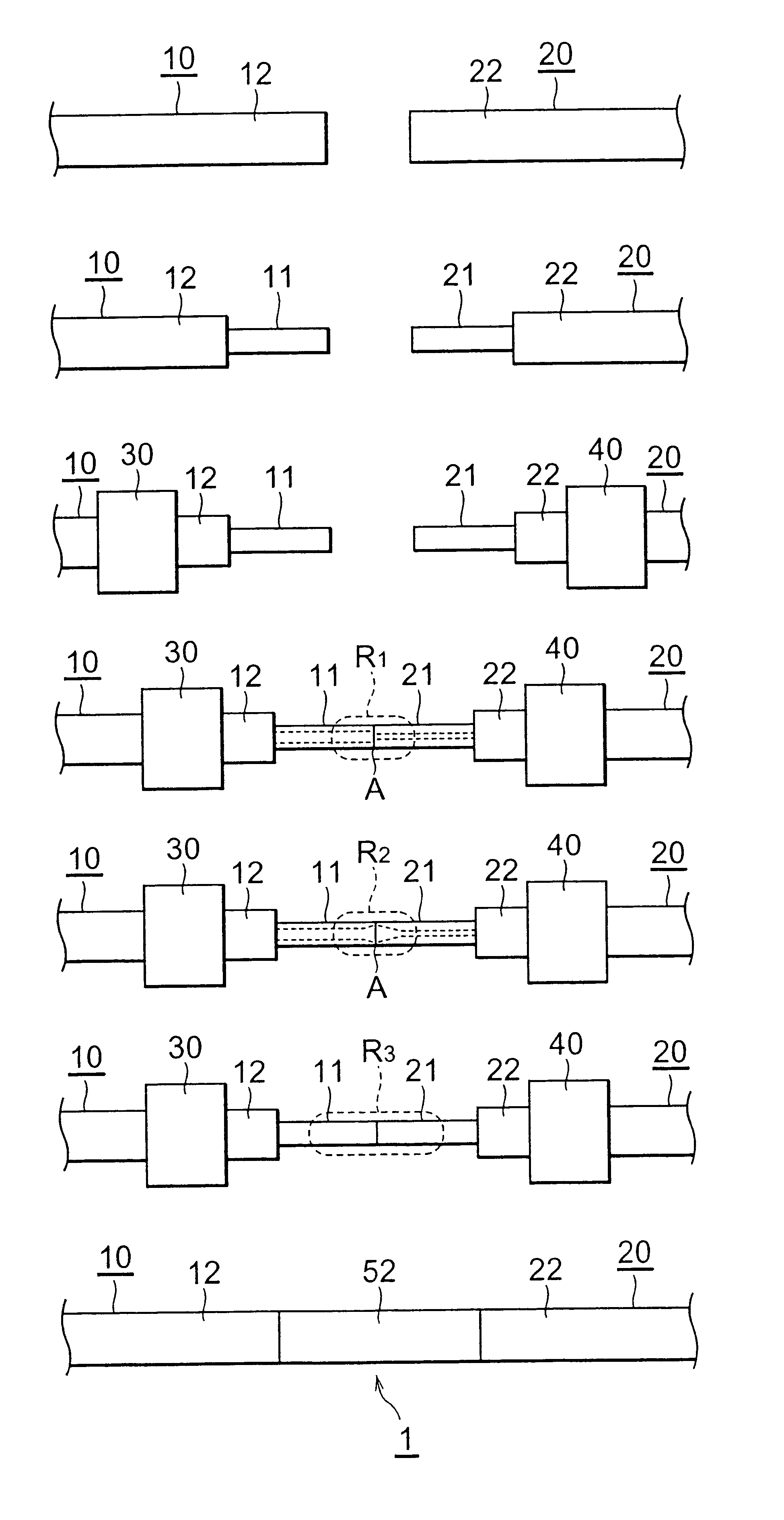
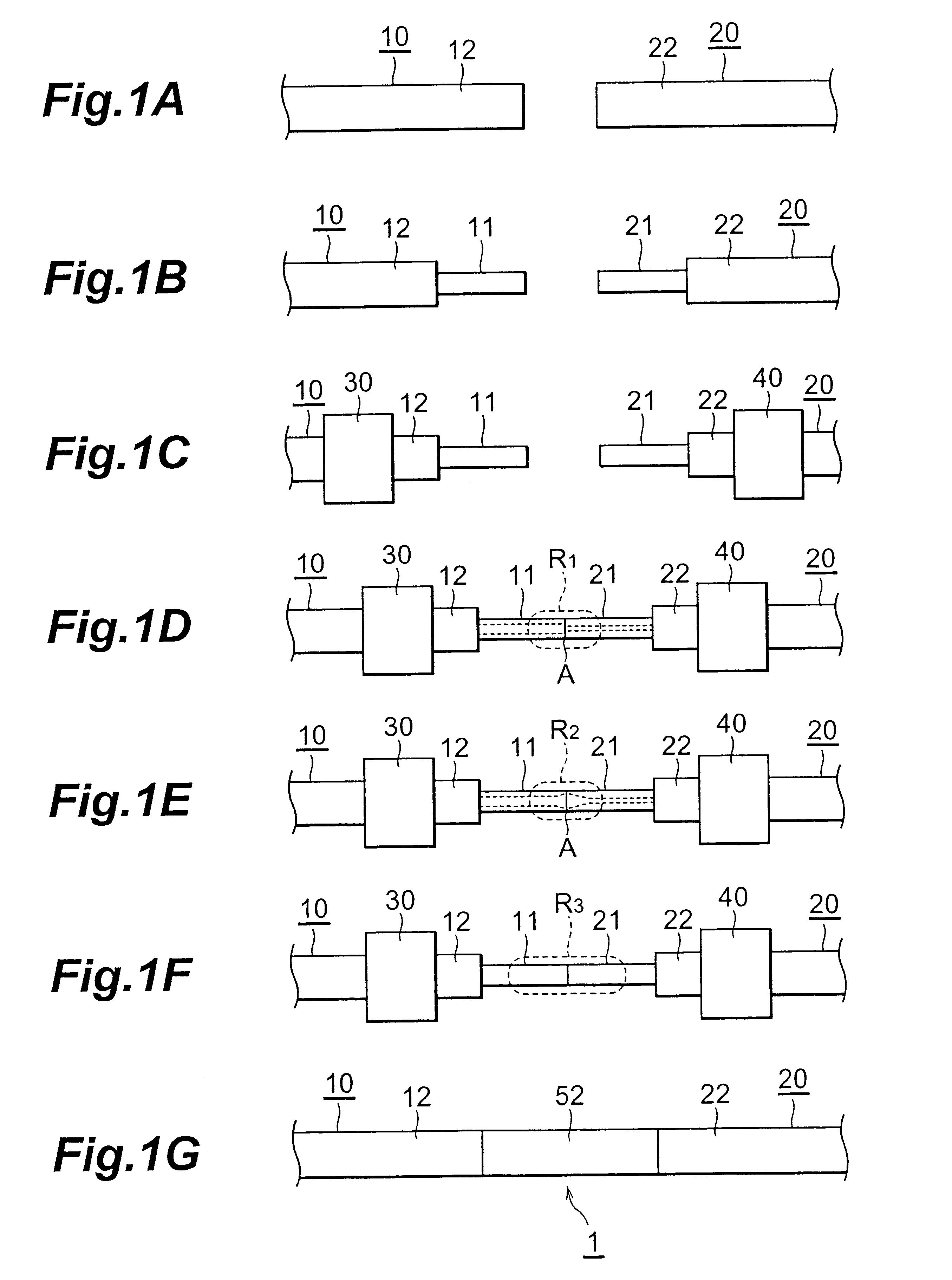
below, a silica-glass-based single-mode optical fiber (the mode field diameter 10 .mu.m) having positive chromatic dispersion at the wavelength of 1.55 .mu.m was used as the optical fiber 10, and a silica-glass-based dispersion compensating optical fiber (the mode field diameter 5 .mu.m) having negative chromatic dispersion at the wavelength of 1.55 .mu.m as the optical fiber 20.

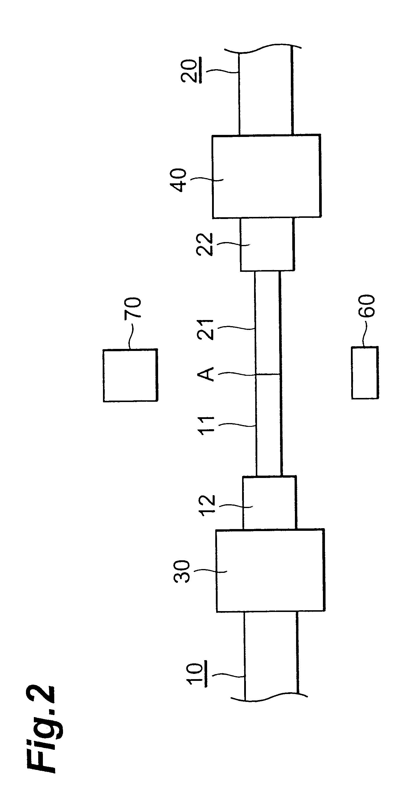
In the first example, arc discharge was used in each of the additive-diffusing step and the thermal-strain-removing step. Specifically, the end faces of the glass fibers 11, 21 were spliced each other by the arc discharge, using the fusion splicer, and in the additive-diffusing step and in the thermal-strain-removing step thereafter the fusion splicer was also used as it was. In the additive-diffusing step, the arc discharge current was 15 mA, the heating temperature was 1300.degree. C., and twenty cycles, each cycle consisting of a heating period of ten seconds and a rest period of sixty seconds, were repea...


PUM

PropertyMeasurementUnit
temperatureaaaaaaaaaa

Abstract

Two optical fibers to be spliced are prepared, coatings of resin are removed from end portions of the respective optical fibers to expose glass fibers, the glass fibers are aligned to each other, an a fusion step is carried out to heat the end faces of the glass fibers to cause fusion thereof to form a fusion-spliced portion. After that, an additive-diffusing step is carried out to diffuse an additive added in the glass fibers around the fusion-spiced portion, by a heat treatment around the fusion-spliced portion, by a heat treatment around the fusion-spliced portion at a first temperature of not less than 800° C. nor more than 1500° C. Further after the additive-diffusing step, a thermal-strain-removing step is carried out to remove thermal strain by a heat treatment of a wider region than heated regions in the fusion splice step and in the additive-diffusing step of the fusion-spliced portion, at a temperature of not less than 500° C. nor more than 1200° C.

Description

1. Field of the InventionThe present invention relates to an optical fiber apparatus having a fusion-spliced portion in which two optical fibers are fusion-spliced, and a fabrication method thereof.2. Related Background ArtAs methods of cascade connection between two optical fibers, there are connector splice and fusion splice. Among these, the fusion splice is a method of aligning two optical fibers each other and heating end faces of the respective fibers to cause fusion thereof, and has the advantage of low splice loss. When two optical fibers of mutually different mode field diameters are spliced by fusion splice, the splice loss increases because of the difference between the mode field diameters. The splice loss can be reduced based on decrease in the difference between the mode field diameters by diffusion of an additive (for example, Ge or F) by heating at a predetermined temperature after the fusion splice. On the other hand, however, the fusion splice had the problem that ...

Claims


Application Information

Patent Timeline
Patent Type & Authority Patents(United States)
IPC IPC(8): G02B6/255
CPCG02B6/2552G02B6/2551
Inventor NAKAMURA, MOTONORIOHGA, YUICHI
Owner SUMITOMO ELECTRIC IND LTD
Why Eureka
Try Eureka