

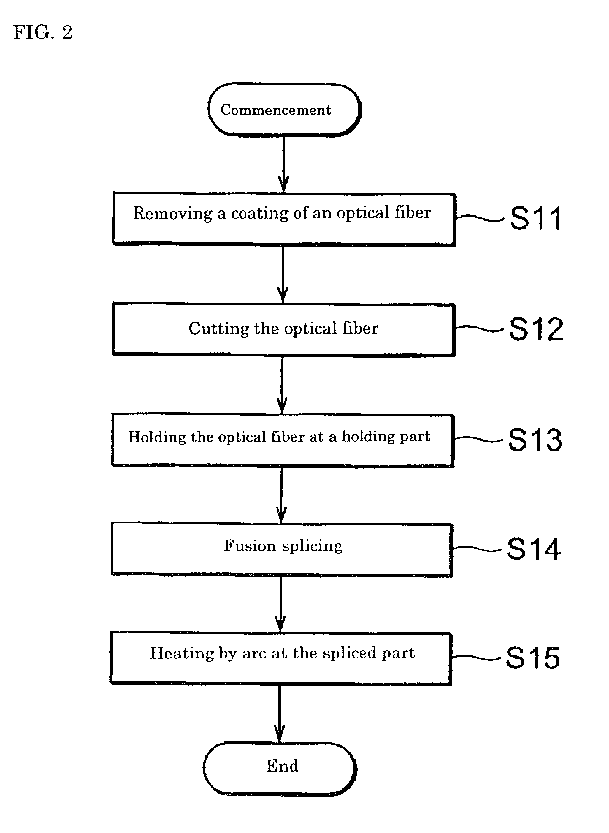
Method for fusion splicing optical fibers and apparatus for heating spliced part by arc
- Summary
- Abstract
- Description
- Claims
- Application Information
AI Technical Summary
Benefits of technology
Problems solved by technology
Method used
Image

Examples
example 1
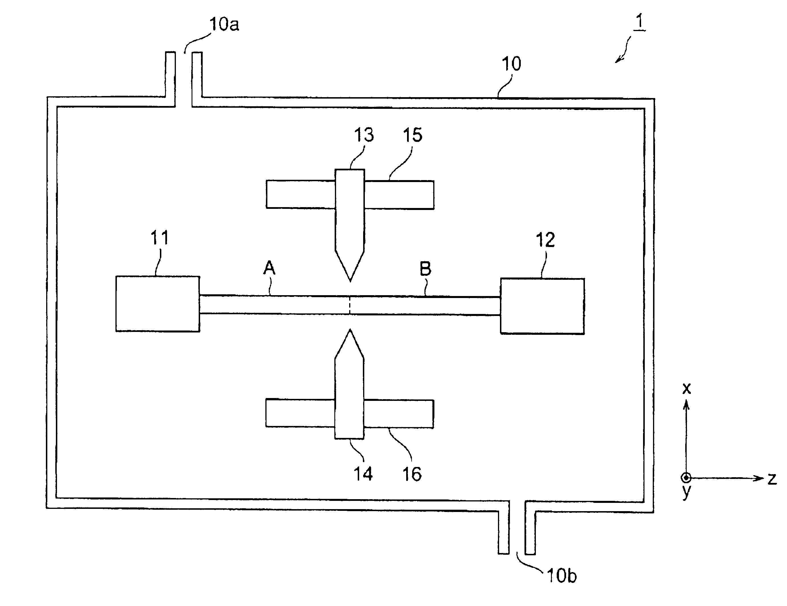
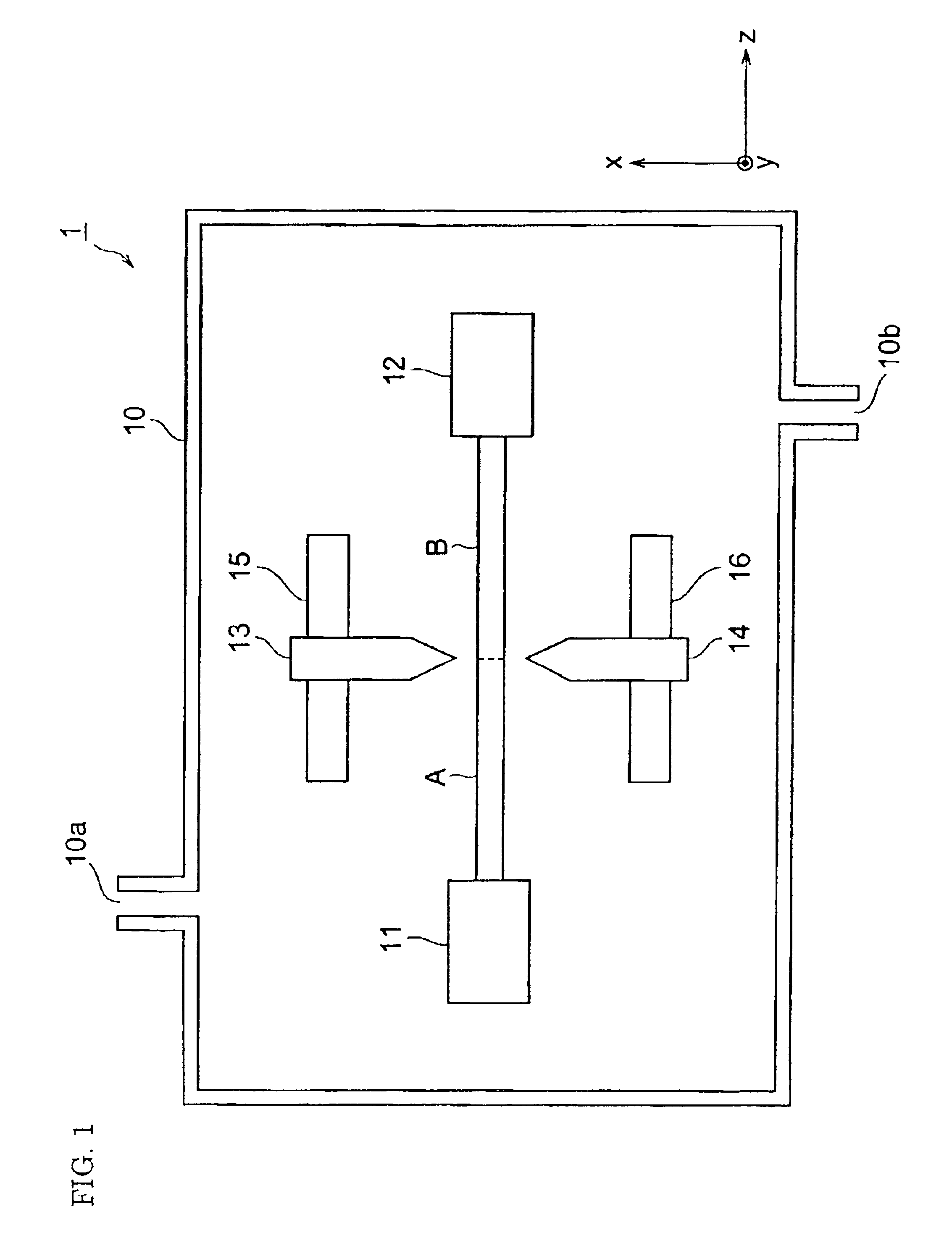
[0058]The optical fibers A and B were fusion-spliced, and arc heating was performed in an argon gas atmosphere. The electric discharge current was set to 13.1 mA, which was a minimum electric current. Arc heating was performed in the range of ±5 mm of the fusion-spliced point of the optical fibers A and B in the Z-axis direction. The flow rate of argon gas in this case was 500 ml / min. The splice loss measured after fusion splicing was 1.35±0.02 dB. On the other hand, the splice loss measured after arc heating was 0.2±0.05 dB.
example 2
[0061]The optical fibers A and B were fusion-spliced, and arc heating was performed in an air atmosphere. The electric discharge current was alternately changed to 13.1 mA and 6 mA while arc heating was performed. The splice loss measured after fusion splicing was 1.35±0.02 dB. On the other hand, the splice loss measured after arc heating was 0.2 dB. The tensile breaking strength measured at n=20 was 4.3 kg on the average.
PUM
| Property | Measurement | Unit |
|---|---|---|
| Flow rate | aaaaa | aaaaa |
| Frequency | aaaaa | aaaaa |
| Frequency | aaaaa | aaaaa |
Abstract
Description
Claims
Application Information