Optical splicer, optical module, and method of producing optical splicer

a technology of optical splicer and optical module, which is applied in the field of optical splicer, can solve the problems of large optical splice loss, and achieve the effects of low loss, reduced splice loss and high accuracy

Inactive Publication Date: 2005-09-22
SUMITOMO ELECTRIC IND LTD
View PDF6 Cites 10 Cited by
  • Summary
  • Abstract
  • Description
  • Claims
  • Application Information

AI Technical Summary

Benefits of technology

[0019] By this production method, the portions where the mode field diameter is enlarged in the optical fibers are inserted into the fiber holes of the optical splice member. For this reason, where two optical fibers are brought into a face-to-face state in each fiber hole, the optical fibers can be spliced with each other with

Problems solved by technology

In consequence, a splice loss will be large

Method used


Image

  • Optical splicer, optical module, and method of producing optical splicer
  • Optical splicer, optical module, and method of producing optical splicer
  • Optical splicer, optical module, and method of producing optical splicer

Examples


Embodiment Construction

[0030] The preferred embodiments of the optical splicer, the optical module, and the production method of the optical splicer according to the present invention will be described below with reference to the drawings.

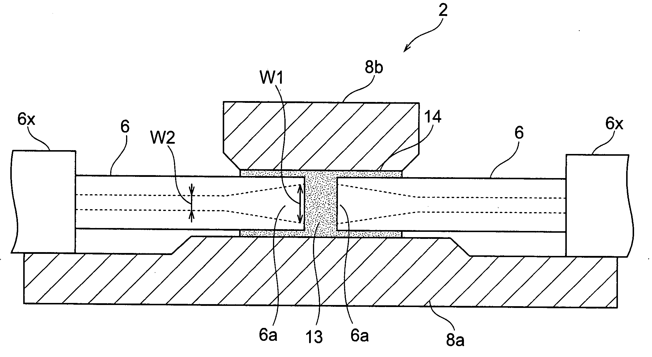
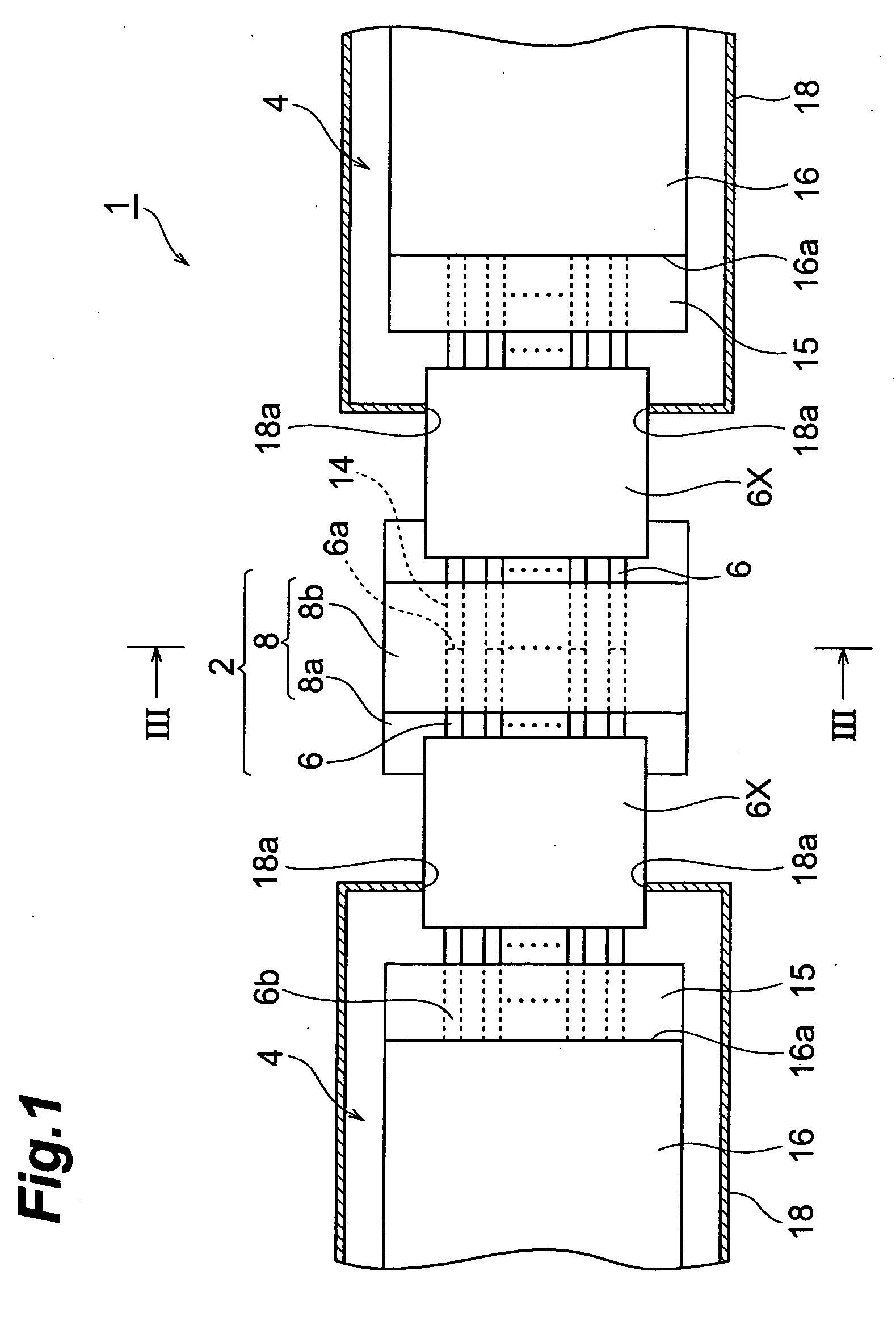
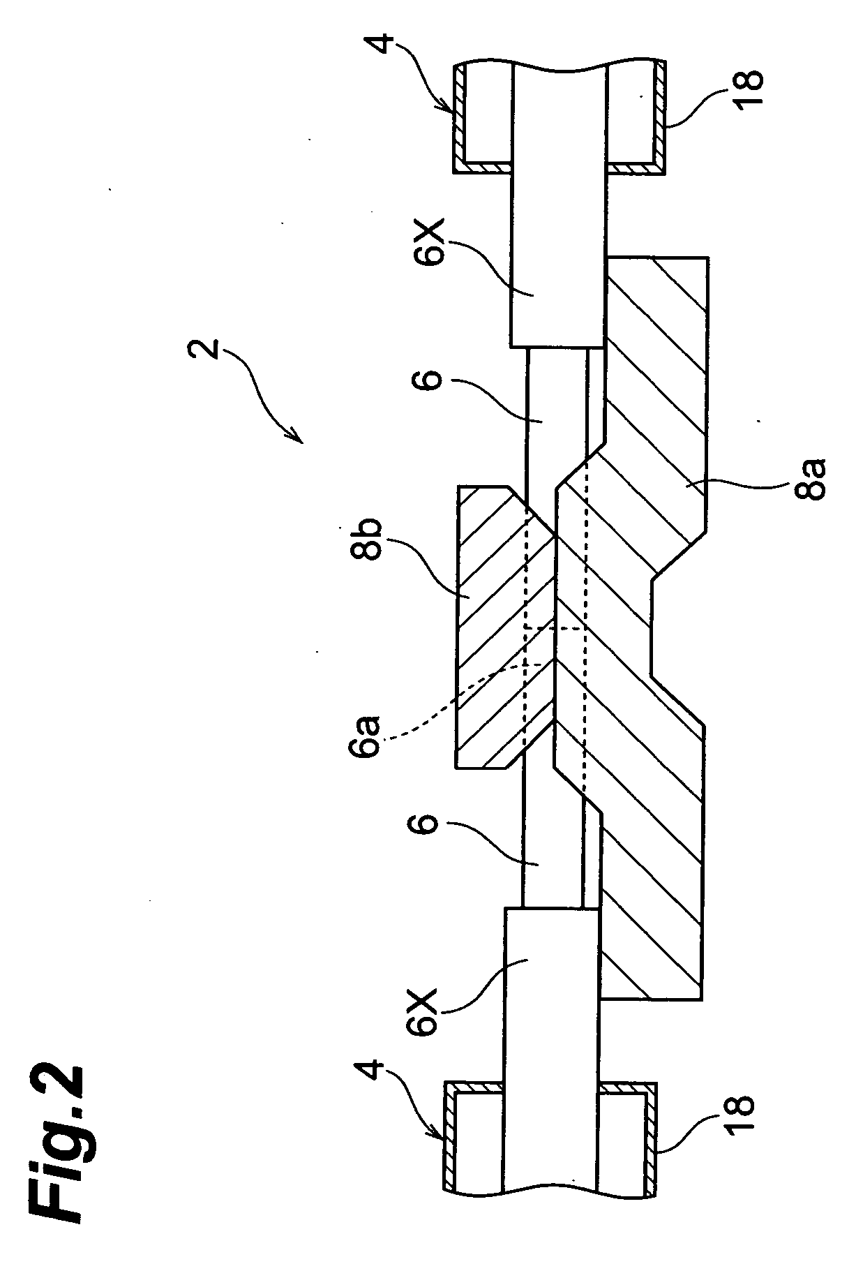
[0031]FIG. 1 is a plan view including a cross section in part, which shows an optical module incorporating an embodiment of the optical splicer according to the present invention, FIG. 2 a vertical sectional view of the optical module shown in FIG. 1, and FIG. 3 a sectional view along line III-III in FIG. 1. FIG. 4 is a vertical, enlarged, sectional view of optical splicer 2.

[0032] As shown in each figure, the optical module 1 of the present embodiment has an optical splicer 2 and two optical devices 4. The optical splicer 2 is a device for splicing two optical devices 4 with each other.

[0033] The optical splicer 2 has an optical splice member 8 for collectively splicing a plurality of optical fibers 6 with a plurality of partner fibers 6. The plurality of optical fib...


PUM


Abstract

An optical splicer 2 according to an embodiment of the present invention has a plurality of optical fibers 6, and an optical splice member 8 having a plurality of fiber holes 14 in each of which a portion including one end 6a of each fiber 6 is inserted, and a mode field diameter W1 in one end 6a of optical fiber 6 is enlarged relative to a mode field diameter W2 in the other portion of optical fiber 6.

Description

BACKGROUND OF THE INVENTION [0001] 1. Field of the Invention [0002] The present invention relates to an optical splicer for splicing optical fibers, an optical module, and a method of producing the optical splicer. [0003] 2. Related Background of the Invention [0004] There are optical splicers for splicing optical fibers by inserting the optical fibers in glass capillaries face to face. [0005] For example, Japanese Patent No. 3154230 describes the optical splicer for splicing a plurality of optical fibers, which comprises a plurality of glass capillaries. In this optical splicer, the central region of each glass capillary is preliminarily filled with an index matching agent. [0006] Japanese Patent Publication No. 7-50219 describes the optical splicer in which a predetermined space is provided between end faces of face-to-face optical fibers and in which the space is filled with an elastic adhesive to effect a splice of the optical fibers. SUMMARY OF THE INVENTION [0007] In the afore...

Claims


Application Information

Patent Timeline
IPC IPC(8): G02B6/24G02B6/255G02B6/38
CPCG02B6/3803
Inventor SAITO, KAZUHITOTAMURA, MITSUAKIIKEJI, MAKIKOHDA, HIROSHIYAMADA, EIICHIRO
Owner SUMITOMO ELECTRIC IND LTD
Why Eureka
Try Eureka