Systems and methods for fabricating low-loss, high-strength optical fiber transmission lines

a technology of optical fiber transmission lines and high-strength fibers, applied in the direction of instruments, lighting and heating apparatus, combustion types, etc., can solve the problems of significant signal loss, achieve high-strength, reduce splice loss, and high-strength

Inactive Publication Date: 2005-05-31
FURAKAWA ELECTRIC NORTH AMERICA INC
View PDF10 Cites 0 Cited by
  • Summary
  • Abstract
  • Description
  • Claims
  • Application Information

AI Technical Summary

Benefits of technology

[0007]The above-described issues and others are addressed by the present invention, aspects of which provide systems and methods for fabricating a low-loss, high-strength optical transmission line. In a method according to an aspect of the invention, a first fiber is spliced to a second fiber at a splice point. The spliced fibers are loaded into a heat treatment station, where a gas torch flame is used to thermally treat a splice region including the splice point, the thermal treatment reducing splice loss between the first and second fibers. While heating the splice region, a dry gas is purged around the torch flame during the heat treatment process to avoid water at the surface of the spliced fibers. According to further aspects of the invention, a purging gas is fed to the torch flame to purge dust particles from the flame, and after the heat treatment has been completed, the torch flame is used to restore the glass surface of the spliced fibers. Additional aspects of the invention provide torch assemblies for fabricating low-loss, high-strength optical fiber transmission lines.

Problems solved by technology

The difference in core diameters results in significant signal loss when a fusion splicing technique is used to connect DCF to SSMF.
However, the high concentration of fluorine dopant in typical DCF limits the application of this technique, because the amount and duration of the heat required to produce the funneling effect may result in an undesirable scattered diffusion of the fluorine dopant.

Method used


Image

  • Systems and methods for fabricating low-loss, high-strength optical fiber transmission lines
  • Systems and methods for fabricating low-loss, high-strength optical fiber transmission lines
  • Systems and methods for fabricating low-loss, high-strength optical fiber transmission lines

Examples


Embodiment Construction

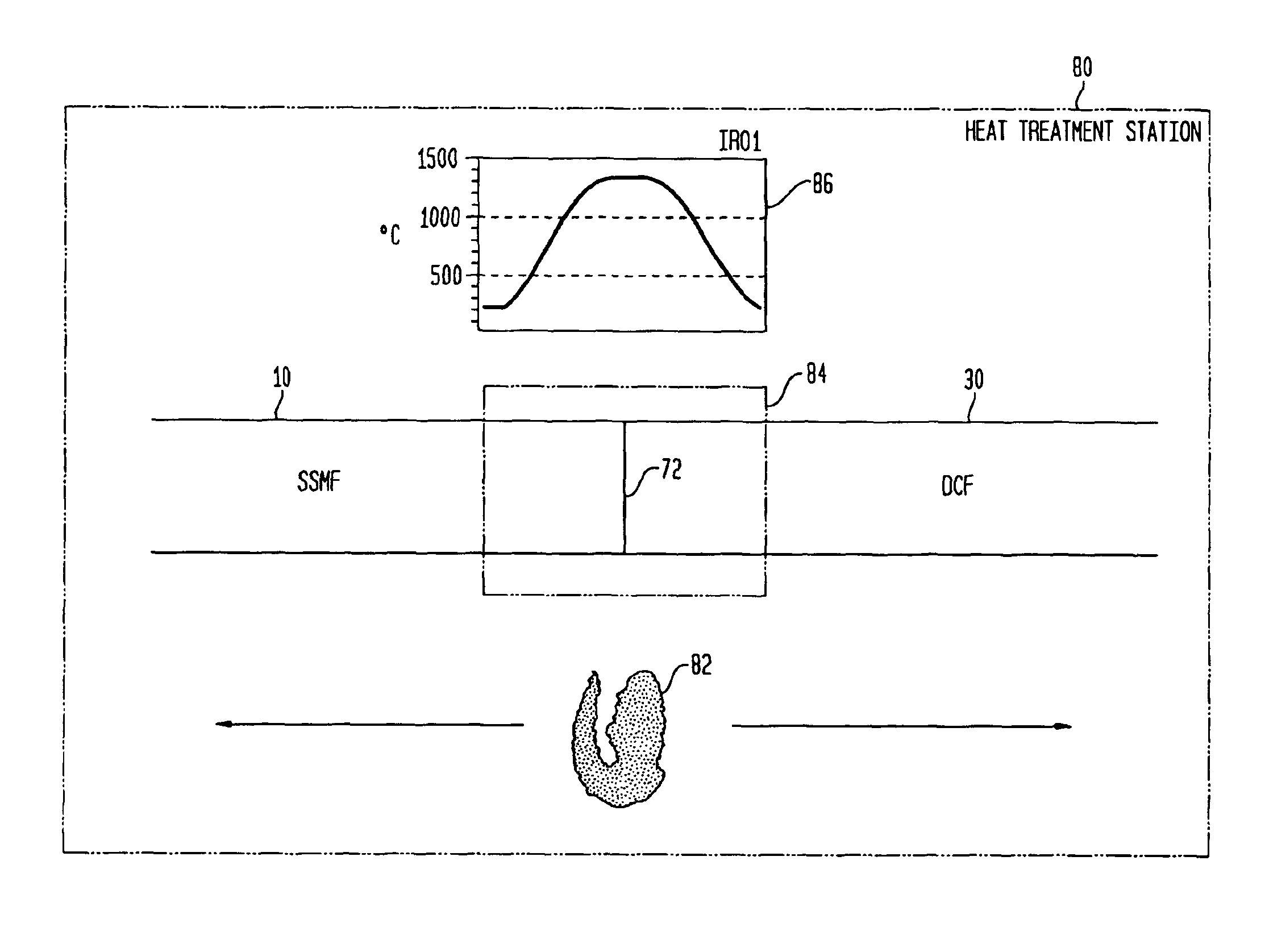
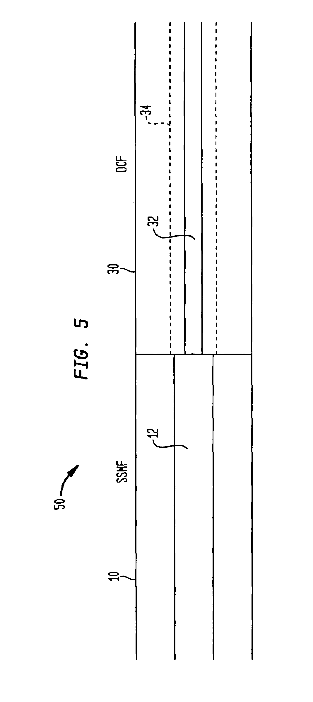
[0028]Aspects of the present invention provide systems and techniques for fabricating a low-loss, high-strength optical transmission line from an inverse dispersion fiber (IDF), such as a dispersion-compensating fiber (DCF), and a second type of fiber, such as a standard single mode fiber (SSMF). It will be appreciated that the systems and techniques described herein may be applied to other types of fibers and fiber dopants without departing from the spirit of the invention. Further, the techniques described below may be practiced singly, or in combination with each other.

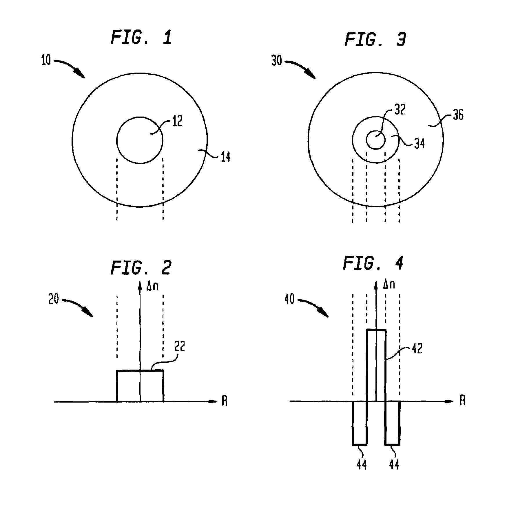
[0029]FIG. 1 shows a cross section of an exemplary length of SSMF 10. SSMF is typically fabricated from silica (SiO2). The SSMF 10 includes a germanium-doped core 12 and an undoped outer cladding layer 14 surrounding the core 12. FIG. 2 shows the refractive index (RI) profile 20 for the SSMF 10. As shown in FIG. 2, the SSMF RI profile 20 includes a central plateau 22 corresponding to the SSMF core 12.

[0030]FIG. 2 s...


PUM

PropertyMeasurementUnit
modefield diameteraaaaaaaaaa

Abstract

Systems and techniques are described for fabricating a low-loss, high-strength optical transmission line. In one described technique, a first fiber is spliced to a second fiber at a splice point. The spliced fibers are loaded into a heat treatment station, where a gas torch flame is used to thermally treat a splice region including the splice point, with the thermal treatment reducing splice loss between the first and second fibers. While heating the splice region, a dry gas is purged around the torch flame during the heat treatment process to avoid water at the surface of the spliced fibers. According to further described techniques, a purging gas is fed to the torch flame to purge dust particles from the flame, and after the heat treatment has been completed, the torch flame is used to restore the glass surface of the spliced fibers. Additionally described are torch assemblies for fabricating low-loss, high-strength optical fiber transmission lines.

Description

BACKGROUND OF THE INVENTION[0001]1. Field of the Invention[0002]The present invention relates generally to improvements to techniques used to splice optical fiber, and more particularly to advantageous aspects of systems and methods for fabricating low-loss, high-strength optical fiber transmission lines.[0003]2. Description of the Prior Art[0004]A new class of optical fibers has recently been developed known as inverse dispersion fibers (IDFs), including dispersion-compensating fibers (DCFs), which have a steeply sloped, negative dispersion characteristic. One use for DCF is to optimize the dispersion characteristics of already existing optical fiber links fabricated from standard single-mode fibers (SSMF) for operation at a different wavelength. This technique is disclosed in U.S. patent application Ser. No. 09 / 596,454, filed on Jun. 19, 2000, assigned to the assignee of the present application, which is hereby incorporated by reference in its entirety.[0005]An important parameter...

Claims


Application Information

Patent Timeline
Patent Type & Authority Patents(United States)
IPC IPC(8): C03B37/10C03B23/00C03B23/043C03B37/15F23D14/40F23D14/00G02B6/255
CPCC03B23/043G02B6/2551F23D14/40C03B37/15
Inventor DIGIOVANNI, DAVID JOHNVENG, TORBEN E.
Owner FURAKAWA ELECTRIC NORTH AMERICA INC
Why Eureka
Try Eureka