Method and apparatus for initializing logical objects in a data storage system

a data storage system and logical object technology, applied in the field of data storage systems, can solve the problems of consuming significant host computer time, affecting the performance of the computer system, and simple copying of data from one file to another can consume significant amount of host computer time,

Inactive Publication Date: 2005-02-24
EMC CORP
View PDF36 Cites 14 Cited by
  • Summary
  • Abstract
  • Description
  • Claims
  • Application Information

AI Technical Summary

Benefits of technology

[0022] According to an aspect of the present invention, an Application Programming Interface (API) is provided that allows a relationship between logical objects on a host computer and storage locations on a storage device to be communicated between the host computer and the storage device. By providing the storage device with knowledge of the relationship between a logical object and the storage locations corresponding to that logical object, data corresponding to the logical object can be manipulated directly by the storage device, rather than by the host computer. Manipulations that can be performed by the storage device include moving non-contiguous bl...

Problems solved by technology

This can negatively impact the performance of the computer system 100 in two ways.
Thus, depending on how many physical blocks of data are to be copied and how many physically blocks of data are moved at a time, even the simple copying of data from one file to another can consume a significant amount of the host computer's time.
Second, even when a particular logical object is small and can be stored in a small number of blocks, the specific location of those blocks at each layer of mapping can dramatically affect the performance of the host computer, causing even a simple read or write of a logical object to consume significant host computer time.
Thus, depending on the mapping performed at each layer of mapping, the copying of data from even...

Method used


Image

  • Method and apparatus for initializing logical objects in a data storage system
  • Method and apparatus for initializing logical objects in a data storage system
  • Method and apparatus for initializing logical objects in a data storage system

Examples


Embodiment Construction

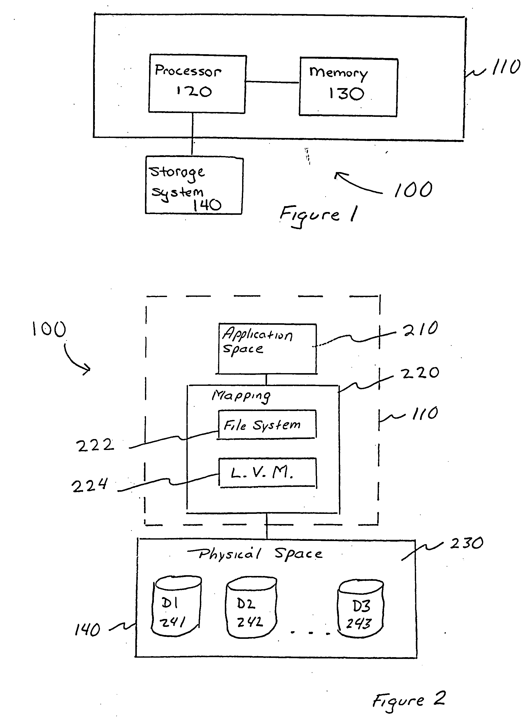
[0051] In one embodiment of the invention, an application program interface (API) is provided between a host computer and a storage system to enable the logical relationship amongst blocks of data in physical space to be communicated from the host computer to the storage device. By providing such knowledge to the storage device, a single I / O operation can be performed on logical objects that are mapped to non-contiguous blocks in physical space on the storage device, at any mapping layer in the computer system. For example, a read or write of a logical object including such non-contiguous blocks of data can be performed in a single I / O operation, thereby providing a more efficient and higher performing computer system than has been conventionally provided. Another example of an operation that can be performed on logical objects including non-contiguous blocks in a single operation is prefetching data from a storage system and storing that data in a cache of the storage system for su...


PUM


Abstract

A method and apparatus for manipulating data in a storage device that is coupled to a host computer. Manipulations that can be performed by the storage device include moving non-contiguous blocks of data between the host computer and the storage device in a single operation. Other manipulations can be performed directly by the storage device without passing data to or from the host computer and include copying data from one logical object that is defined on the host computer to another, initializing, backing-up, transforming, or securely deleting a logical object that is defined by the host computer with a single command. In one embodiment, an application programming interface is provided that allows a relationship between logical objects on a host computer and storage locations on a storage device to be communicated between the host computer and the storage device. By providing the storage device with knowledge of the relationship between a logical object and the storage locations corresponding to that logical object, data corresponding to the logical object can be manipulated directly by the storage device, rather than by the host computer. In another embodiment, a graphical visualization routine is provided that displays the global mapping of a logical object to a set of physical blocks on the storage device for each layer of mapping below the logical object.

Description

CROSS REFERENCE TO RELATED APPLICATIONS [0001] This application is a continuation of prior application Ser. No. 09 / 107,684, filed Jun. 30, 1998, entitled METHOD AND APPARATUS FOR INITIALIZING LOGICAL OBJECTS IN A DATA STORAGE SYSTEM, which application is incorporated herein by reference.FIELD OF THE INVENTION [0002] The present invention relates to data storage systems. More particularly, the present invention is directed to a method and apparatus for manipulating logical objects in a data storage system. DESCRIPTION OF THE RELATED ART [0003] Computer systems typically include one or more storage devices. FIG. 1 is a block diagram of such a typical computer system 100. The system 100 includes a host computer 110, having a processor 120 and a memory 130, and a storage system 140. The storage system 140 can be of any of a number of types (e.g., a tape storage device, a floppy diskette storage device, a disk storage device, etc.), or can include a combination of different types of stor...

Claims


Application Information

Patent Timeline
IPC IPC(8): G06F3/06
CPCG06F3/061G06F3/0683G06F3/064
Inventor BLUMENAU, STEVEN M.TAMER, PHILIP E.VISHLITZKY, NATAN
Owner EMC CORP
Why Eureka
Try Eureka