Stripping tool for fiber optic cables

a fiber optic cable and tool technology, applied in the direction of optics, instruments, optical elements, etc., can solve the problem of limiting the extent of relative displacement in the operating member, and achieve the effect of reliable stripping accuracy

Inactive Publication Date: 2005-03-03
CONNECTOOL
View PDF6 Cites 26 Cited by
  • Summary
  • Abstract
  • Description
  • Claims
  • Application Information

AI Technical Summary

Benefits of technology

[0006] The universal fiber optic stripping tool according to the present invention is quite versatile and affords reliable stripping accuracy for multiple optic fiber cable assemblies, the removal of the outer jackets from 2.0 mm to 2.4 mm optic fiber cables and 2.8 mm to 3.0 mm optic fiber cables, the outer jackets from 2.0 mm to 3.0 mm loose tube optic fiber cables, the stripping of the 900 μm buffer layer of a loose buffer without removal of the acrylate layer, and the stripping of the buffer and acrylate layers off of 900 / 125 μm and 250 / 125 μm optic fibre cables.

Problems solved by technology

Furthermore, the housing of the calibration means limits the extent of relative displacement in the operating members in the spring-biased opening direction of displacement.

Method used


Image

  • Stripping tool for fiber optic cables
  • Stripping tool for fiber optic cables
  • Stripping tool for fiber optic cables

Examples


Embodiment Construction

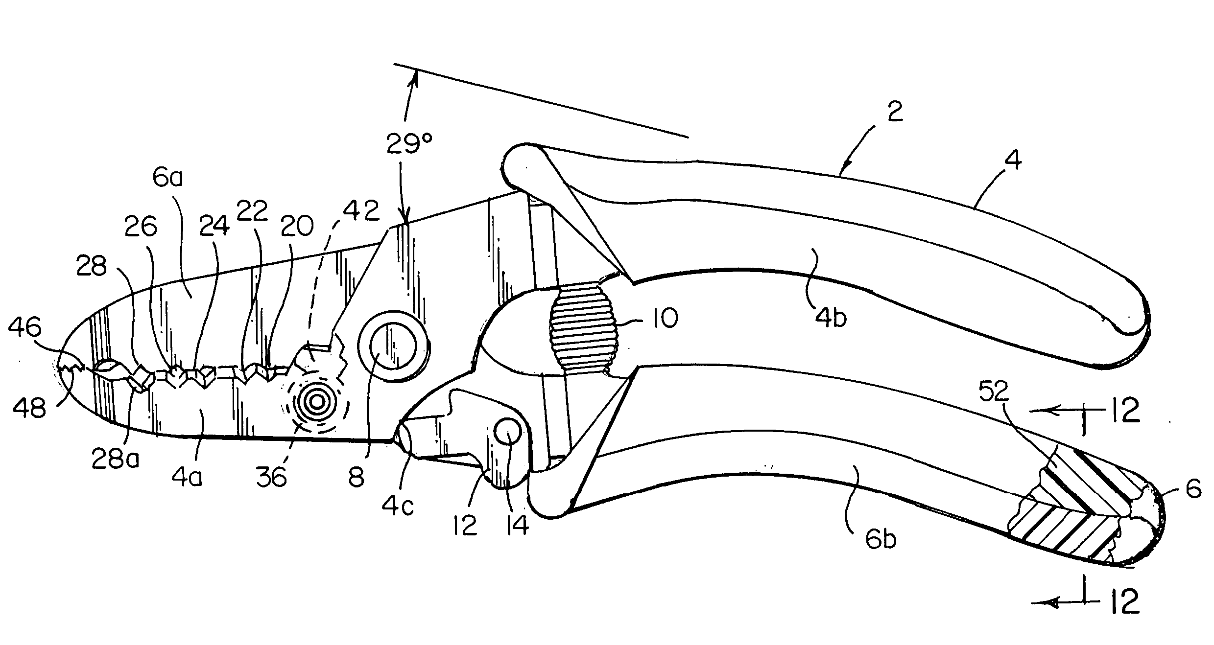
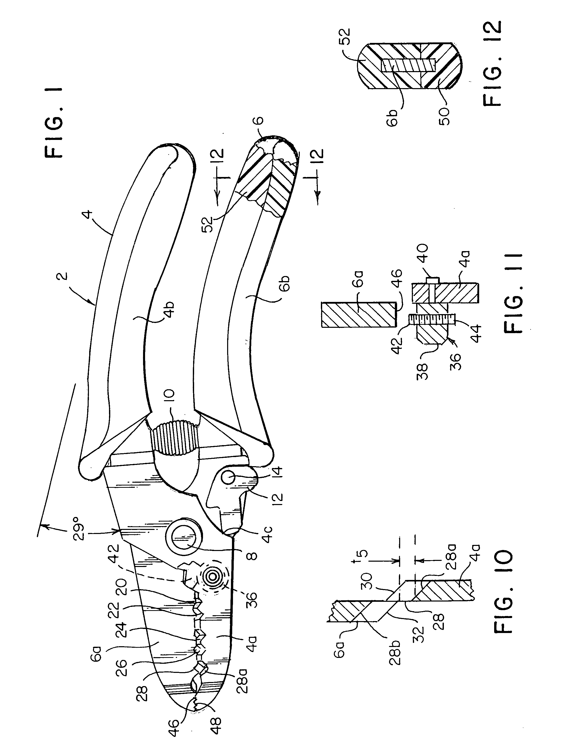
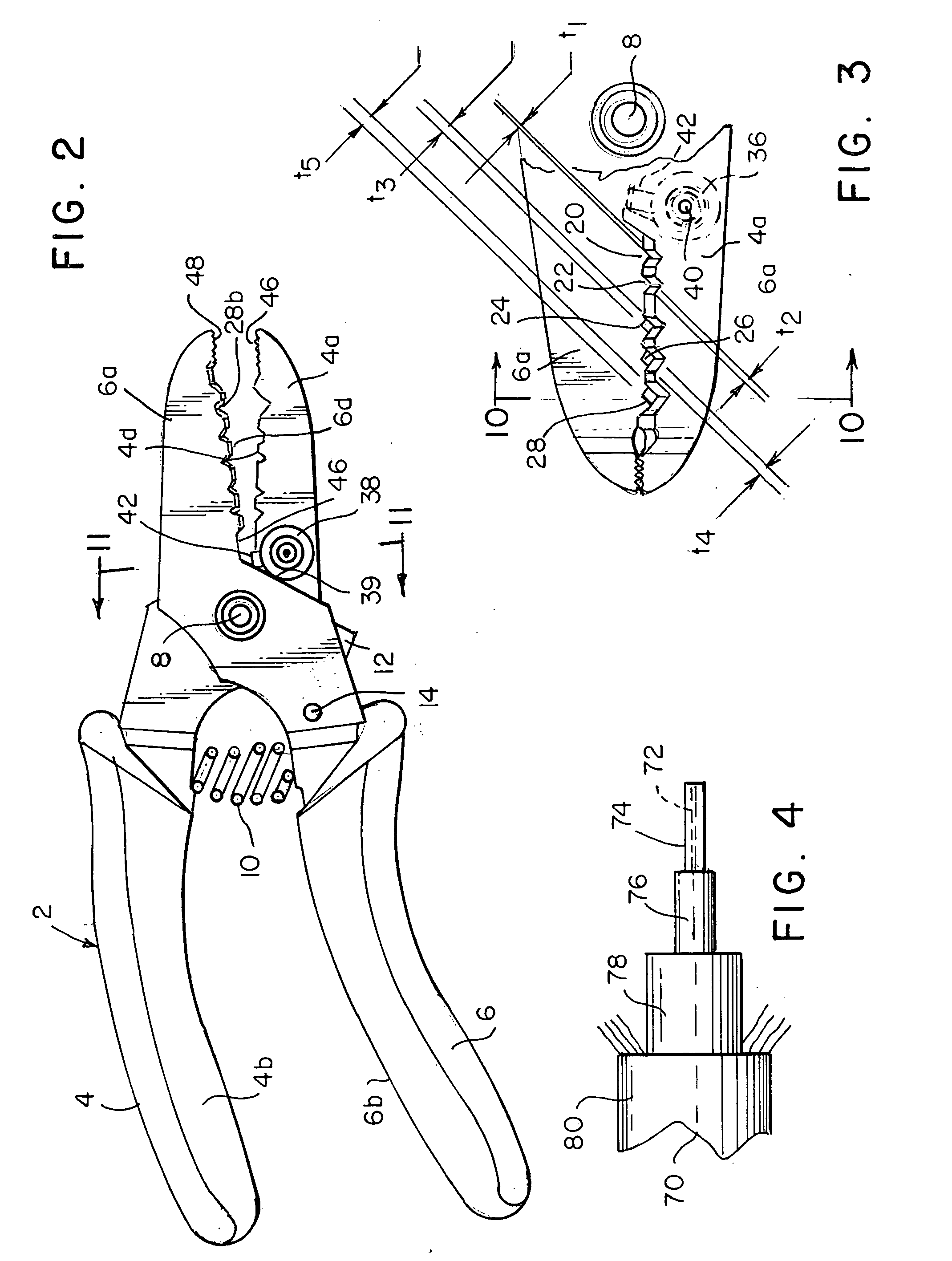
[0017] Referring first more particularly to FIGS. 1 and 2, the fiber optic stripping tool 2 includes a pair of operating members 4 and 6 that are pivotally connected intermediate their ends by pivot pin 8, thereby to permit pivotal displacement of the members between the closed condition of FIG. 1 and the open condition of FIG. 2. The operating members are formed of a hard metal, such as high carbon steel. A pair of stripping portions 4a and 6a are formed on one side of the pivot pin 8, and a pair of handle portions 4b and 6b are defined on the opposite side of the pivot pin. Compression spring 10 normally biases the operating members apart toward the open condition of FIG. 2. As shown in FIG. 1, an L-shaped locking lever 12 is pivotally connected by a second pivot pin 14 between a locked condition shown in FIG. 1, to an unlocked condition shown in FIG. 2. When in the locked condition of FIG. 1, the locking member engages the stop surface 4c on the operating arm 4, thereby to lock t...


PUM

PropertyMeasurementUnit
angleaaaaaaaaaa
sizeaaaaaaaaaa
sizeaaaaaaaaaa

Abstract

A scissors-type fiber optic cable stripping tool includes a pair of operating members pivotally connected intermediate their ends, thereby to define stripping portions and handle portions on opposite sides of a pivot pin. The adjacent surfaces of the stripping portions are provided with a plurality of longitudinally spaced V-shaped recesses that cooperate when the operating members are pivoted to the closed position to define stripping openings that progress in size in the direction away from the pivot pin. Spring means bias the operating members toward an open condition, and locking means serve to lock the operating members in the closed condition for transport of the tool. The stripping openings of progressively increasing size have machined surfaces that define knife edges are adapted to sever the outer concentric insulation layers of various sizes and types of fiber optic cables, including the outer jacket of a 2.0 mm to 2.4 mm optic fiber cable, the outer jacket of a 2.8 to 3.0 mm optic fiber cable, the outer jacket of a 2.0 mm to 3.0 mm loose tube optic fiber cable, the 900 μm buffer layer of a loose buffer optic cable, and the buffer and acrylate layers of 900/125 μm and 250/125 μm fiber optic cables.

Description

FIELD OF THE INVENTION [0001] A versatile scissors-type stripping tool for removing the outer layer of insulation from a plurality of types and sizes of optic fiber cables, including a pair of operating members that are pivotally connected intermediate their ends to define on each operating member on opposite sides of a pivot pin a stripping portion and a handle portion. A plurality of recesses having knife edges are provided longitudinally on the adjacent sides of the stripping portions, which recesses cooperate when the operating members are in the closed condition to define stripping openings the size of which progressively increases in the direction away from the pivot pin. BACKGROUND OF THE INVENTION BRIEF DESCRIPTION OF THE PRIOR ART [0002] Insulation stripping tools for stripping insulation from electrical conductors are well known in the patented prior art, as shown by the inventors's prior U.S. Pat. No. 6,526,661, which is assigned to the same assignee as the present invent...

Claims


Application Information

Patent Timeline
Patent Type & Authority Applications(United States)
IPC IPC(8): G02B6/44
CPCG02B6/4497G02B6/566
Inventor SHUTTS, LESLIE B.CHENG, YIN HOSEI, HUANG DE
Owner CONNECTOOL
Why Eureka
Try Eureka