
Cable special stripping cutter

A cutting tool and cable technology, which is applied in the direction of dismantling/armouring cable equipment, etc., can solve the problems that the cutting tool cannot be adjusted, fine-tuning cannot be realized, and the manufacturing cost is high, and the effect of simple structure, improved stripping and cutting accuracy, and ingenious conception

Inactive Publication Date: 2016-08-10
STATE GRID CORP OF CHINA +1
View PDF4 Cites 0 Cited by
  • Summary
  • Abstract
  • Description
  • Claims
  • Application Information

AI Technical Summary

Problems solved by technology

[0003] The main problems are: the existing stripping cutter has complex structure and high manufacturing cost; the cutter is installed on the fixed platform through the mounting bracket, and a rectangular spring clip is arranged between the mounting bracket and the fixed platform to realize the up and down and left and right adjustment of the cutter , the adjustment of the mounting bracket is rough adjustment, fine adjustment cannot be realized, and the tool itself cannot be adjusted, which has great limitations

Method used


Image

  • Cable special stripping cutter
  • Cable special stripping cutter

Examples


Embodiment Construction

[0012] The present invention will be further described below in conjunction with drawings and embodiments.

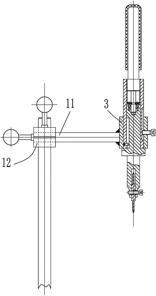
[0013] figure 1 Shown is a special stripping and cutting tool for cables, which is mainly composed of a hob 1, an adjustment rod 2, an outer sleeve 3, a middle sleeve 4, an inner shaft 5, a compression screw 6, and a head screw 7. The inner shaft 5, the middle sleeve 4, and the overcoat 3 are installed coaxially from the inside to the outside, and the adjusting rod 2 and the inner shaft 5 are also installed coaxially, and the adjusting rod 2 is positioned above the inner shaft 5. A gap 5a is formed at the lower end of the inner shaft 5, and the hob 1 is sheathed on the bolt, and is mounted on the inner shaft 5 through the bolt, and the hob 1 is rotatably installed in the gap 5a. The distance from the axis of the hob 1 to the bottom of the notch 5a is smaller than the radius of the hob 1 to ensure that the blade of the hob 1 is located outside the notch 5a to cut cables...


PUM


Abstract

The invention discloses a peeling and cutting tool for cables. The peeling and cutting tool comprises a hob (1), an adjusting rod (2), an outer sleeve (3), a middle sleeve (4), an inner shaft (5), a pressing screw (6) and a set screw (7), wherein the hob (1), the adjusting rod (2), the outer sleeve (3), the middle sleeve (4), the inner shaft (5), the pressing screw (6) and the set screw (7) are arranged in a coaxial mode, the pressing screw horizontally penetrates through the outer sleeve and then abuts against a stopping groove (4a) of the middle sleeve, the set screw penetrates through the middle sleeve and then is stretched into a rotation stopping groove (5c) of the inner shaft, the threaded section (2b) of the adjusting rod is connected with the upper portion of the middle sleeve through threads, a shaft neck (2d) is arranged in the middle of a push rod section (2c), the lower portion of the push rod section is inserted into a cylinder hole which corresponds to the top of the inner shaft, two semi-circular rings are arranged on the shaft neck, the semi-circular rings has the same height with the shaft neck and are buckled with the shaft neck, and the two semi-circular rings are fixed on the inner shaft through fastening screws (9) respectively. The peeling and cutting tool for the cables is simple in structure and ingenious in conception, achieves the objective that a cable cutting tool can not only conduct rough adjustment but also conduct fine adjustment, is combined with the adjusting function of a tool installation frame and enables the tool to be more conveniently adjusted in a labor-saving mode.

Description

technical field [0001] The invention relates to a cutter structure, in particular to a special cutter for radial or axial stripping and cutting of cables. Background technique [0002] Cable stripping is divided into axial stripping and radial stripping. Axial stripping and radial stripping are completed by different stripping mechanisms, but the stripping tools used for axial stripping and radial stripping have interchangeability. First, the stripping cutter in the axial stripping mechanism moves along the extension direction of the cable axis to complete the axial stripping and cutting of the cable insulation layer and armor layer; then the stripping cutter in the radial stripping mechanism moves around The outer circumference of the cable rotates to complete the radial stripping and cutting of the cable insulation layer and armor layer. The stripping cutter in the axial stripping mechanism is located above the horizontal worktable, and the stripping cutter in the radial...

Claims


Application Information

Patent Timeline
Patent Type & Authority Patents(China)
IPC IPC(8): H02G1/12
Inventor 向平阳明向鹏丁力熊真春王世强欧儒春胡跃武王坤华杨永灵王浩江浩丁玲平帅靖树罗杨朱宝良刘启毅
Owner STATE GRID CORP OF CHINA
Learn More