Frame structure of an electrostatic precipitator

Inactive Publication Date: 2005-03-03
HUNG HSING ELECTRIC CO LTD
View PDF13 Cites 12 Cited by
  • Summary
  • Abstract
  • Description
  • Claims
  • Application Information

AI Technical Summary

Benefits of technology

[0011] The electrostatic precipitator frame includes several first and second metallic boards for opposite charges to be deposited on, metallic rods, and holding tubes made of insulator. The boards are positioned one over another with each of the first boards being between respective two second boards. Each board has big holes and small holes; the big holes of the first boards are aligned with corresponding small holes of the second boards, and the small holes of the first boards are aligned with corresponding big holes of the second boards. The metallic rods are each inserted through corresponding fi

Problems solved by technology

Consequently, the insulating sleeves take much material to manufactured, a

Method used


Image

  • Frame structure of an electrostatic precipitator
  • Frame structure of an electrostatic precipitator
  • Frame structure of an electrostatic precipitator

Examples


Embodiment Construction

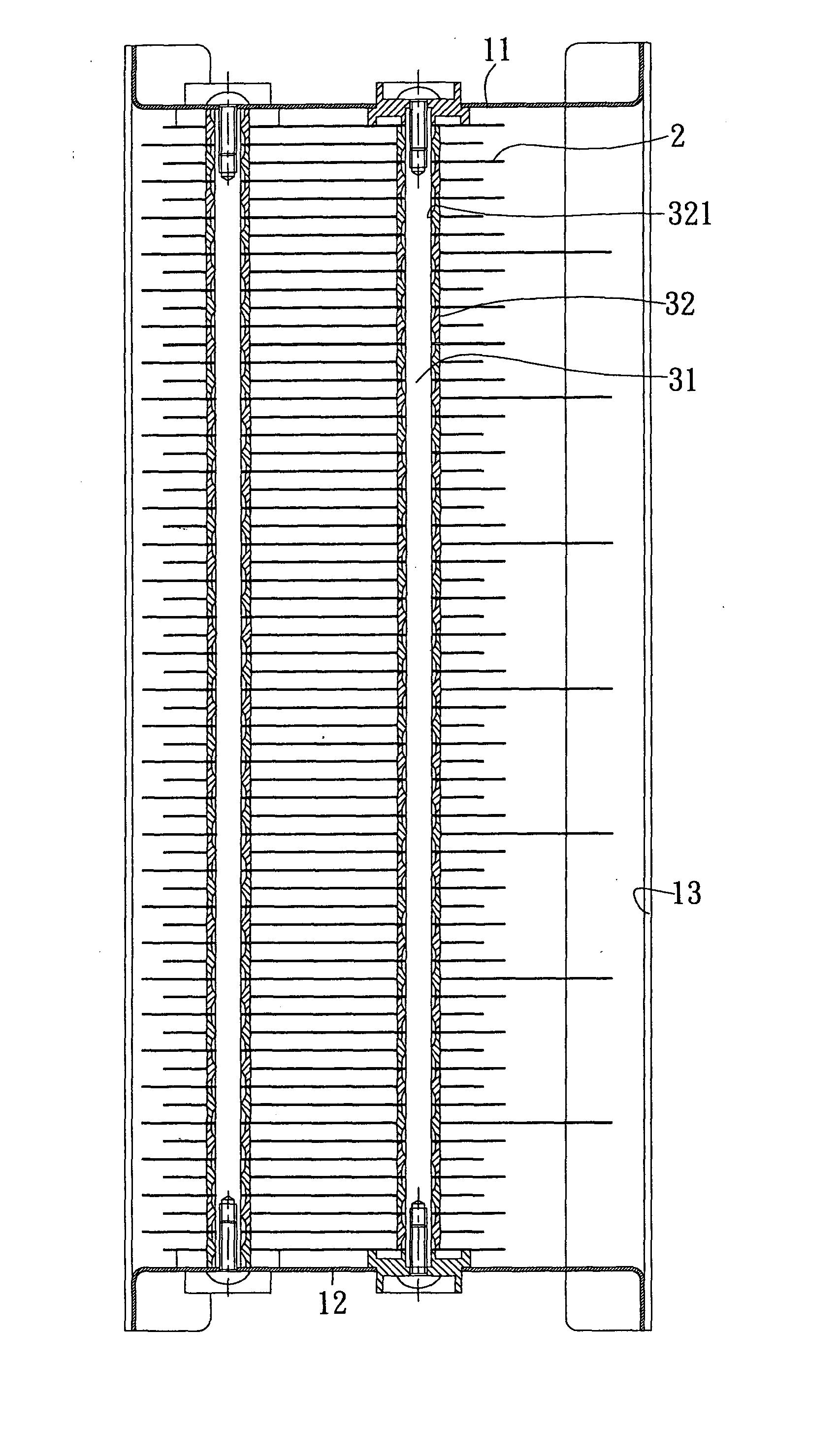
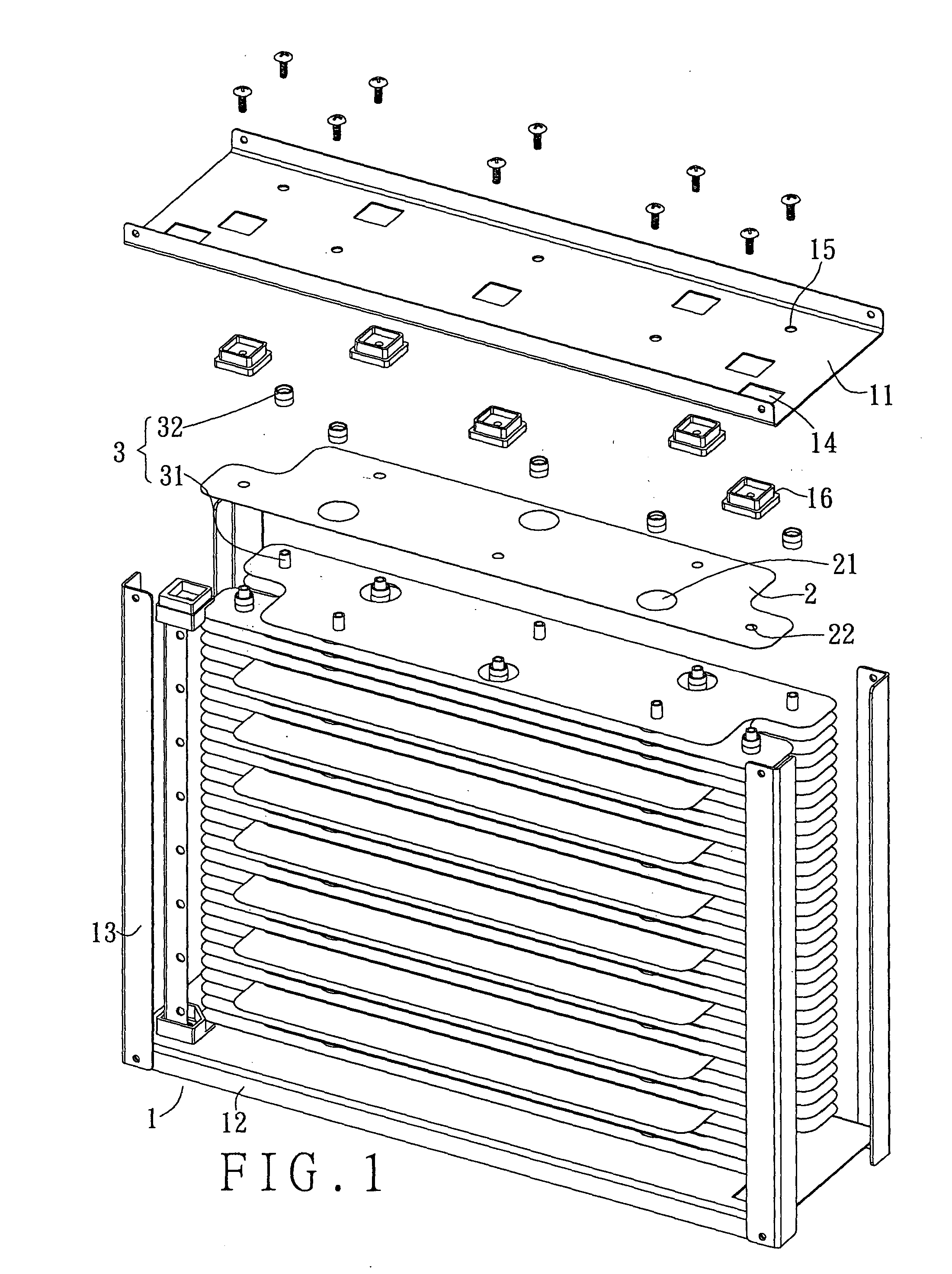
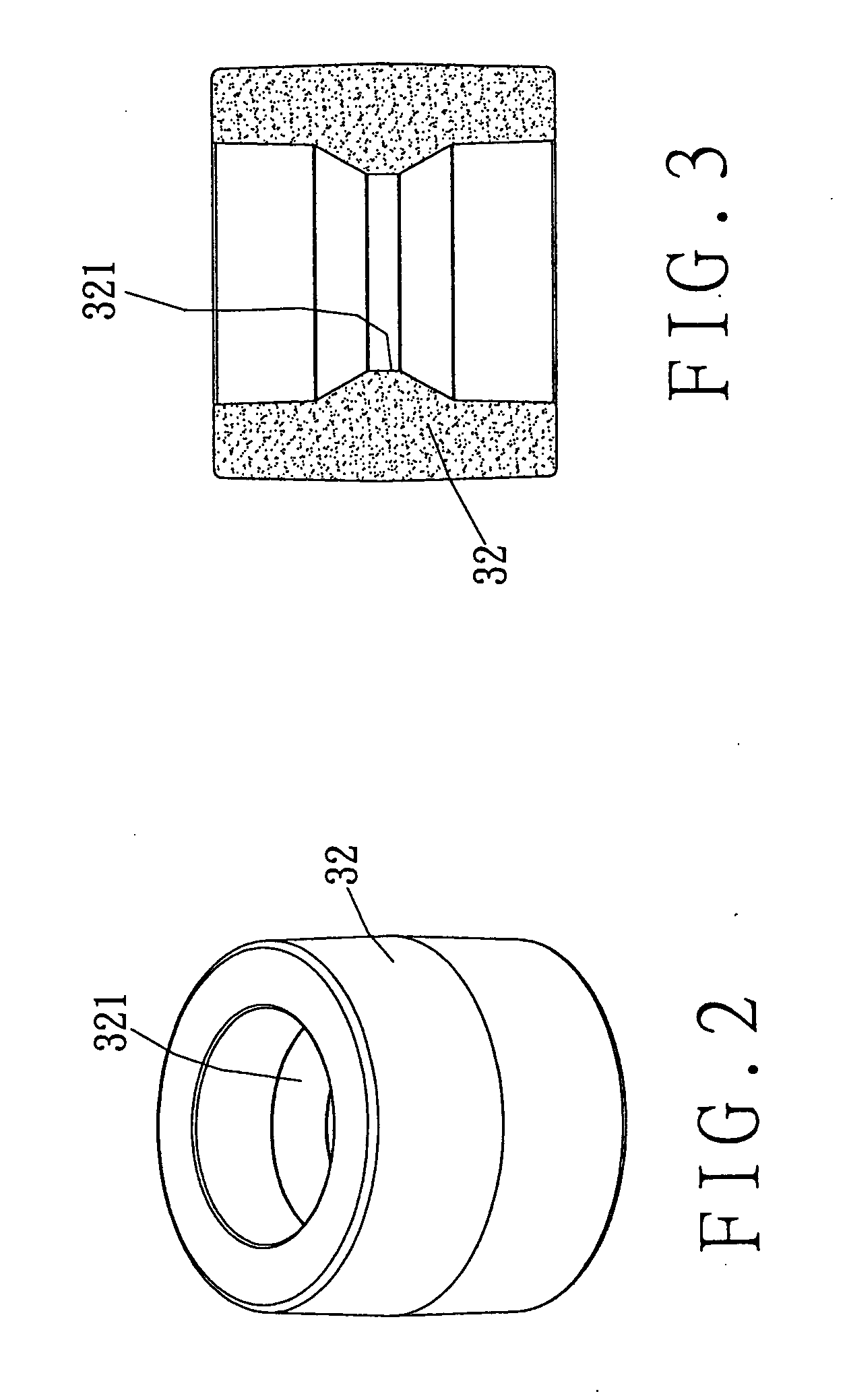
[0021] Referring to FIGS. 1 and 2, a preferred embodiment of an electrostatic precipitator frame 1 in the present invention includes an upper board 11, a lower board 12, support rod parts 13, several metallic boards 2, and connecting rods 3, each of which consists of a metallic rod 31, and several holding tubes 32 made of insulator.

[0022] The support rod parts 13 are coupled to edges of the upper board 11 at upper ends, and edges of the lower board 12 at lower ends thereof. Each of the boards 11 and 12 has through holes 14, and through holes 15, which are smaller than the through holes 14.

[0023] Each of the metallic boards 2 has holes 21, and locating holes 22. The diameter of the holes 21 is larger than the outer diameter of the holding tubes 32 while the diameter of the locating holes 22 is smaller than the outer diameter of the holding tubes 32. In addition, the diameter of the locating holes 22 is the same as that of the metallic rods 31 such that when inserted in one locating...


PUM


Abstract

An electrostatic precipitator includes first and second metallic boards for opposite charges to be deposited on, metallic rods, and holding tubes; the boards are positioned one over another with each first board being between respective two second boards; each board has big holes and small holes; the big holes of the first boards are aligned with corresponding small holes of the second boards, and the small holes aligned with corresponding big holes of the second boards; the rods are each inserted through all of the boards to be only in contact with the edges of corresponding small holes; the tubes are positioned around the rods, and inserted through respective big holes such that the boards are spaced; each tube has an annular protrusion on an inner side, and hollows next to the annular protrusions such that each tube can be produced with reduced materials while the rods can be in contact with the protrusions.

Description


Claims


Application Information

Patent Timeline
Owner HUNG HSING ELECTRIC CO LTD
Why Eureka
Try Eureka