Structure of fuel pump installation area for two-wheeled vehicle

Inactive Publication Date: 2005-03-03
HONDA MOTOR CO LTD
View PDF11 Cites 24 Cited by
  • Summary
  • Abstract
  • Description
  • Claims
  • Application Information

AI Technical Summary

Benefits of technology

[0016] It is a object of the present invention to enhance the stiffness of an installation area of a fuel pump built in the fuel tank to the fuel tank, and to enhance also t

Problems solved by technology

Thus, the workability durin

Method used


Image

  • Structure of fuel pump installation area for two-wheeled vehicle
  • Structure of fuel pump installation area for two-wheeled vehicle
  • Structure of fuel pump installation area for two-wheeled vehicle

Examples


Embodiment Construction

[0047] Hereinafter, with reference to the accompanying drawings, the description will be made of the best mode for carrying out the present invention. In this respect, the drawings will be viewed in the direction of the symbol.

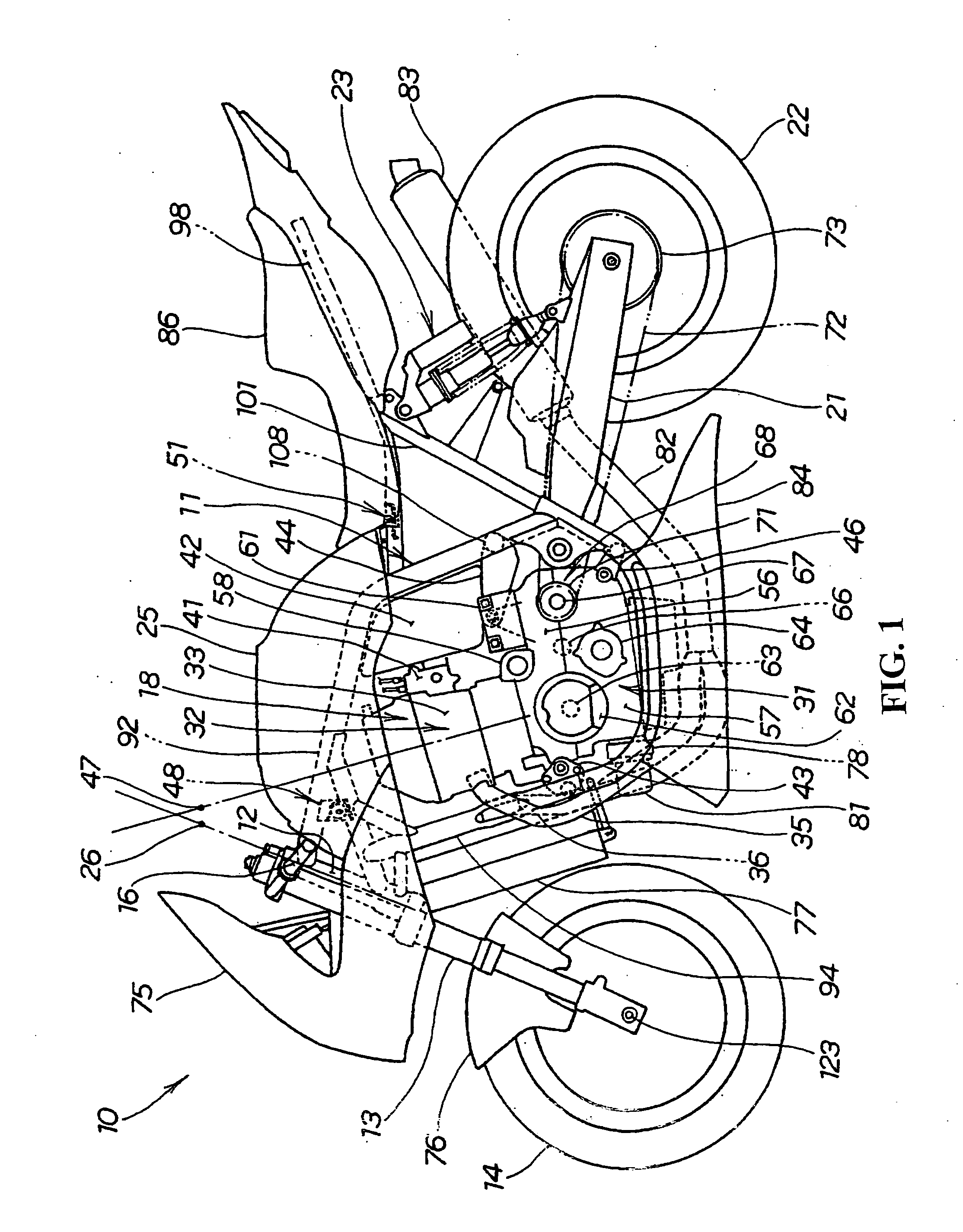
[0048]FIG. 1 is a side view showing a two-wheeled vehicle according to the present invention. A motorcycle 10 is a vehicle including a head pipe 12 provided in the front part of a cradle type body frame 11 with a front fork 13 installed in such a manner as to be freely steered. At the lower end of this front fork 13, a front wheel 14 is installed. On the upper part of the front fork 13, handlebars 16 are installed. On the inside of the body frame 11, an engine 18 is installed. In the lower part of the rear part of the body frame 11, a swing arm 21 is installed in such a manner as to be freely swingable in the up-and-down direction. At the rear end of the swing arm 21, a rear wheel 22 is installed. Between the upper part of the rear part of the body frame 11 a...


PUM

PropertyMeasurementUnit
Areaaaaaaaaaaa
Stiffnessaaaaaaaaaa

Abstract

A fuel pump installation area for a vehicle for enhancing the stiffness of the fuel pump built in a fuel tank and for enhancing the stiffness of an installation area of a tank installation stay on the fuel tank side. In a motorcycle in which a fuel tank is installed to the body frame and a fuel pump is provided within this fuel tank, the fuel pump is installed to the fuel tank via a pump installation member. To the pump installation member, a tank installation stay for fixing the fuel tank to the body frame is installed. The left and right side walls may be formed by depressing the center of the underside of the fuel tank upwardly over the front and the rear. Concave-shaped engaging members are installed by engaging left and right convex portions provided on the body frame with these engaging members, respectively.

Description

CROSS-REFERENCE TO RELATED APPLICATIONS [0001] The present application claims priority under 35 USC 119 to Japanese Patent Application Nos. 2003-282204 and 2003-282206 both filed on Jul. 29, 2003 the entire contents thereof are hereby incorporated by reference. BACKGROUND OF THE INVENTION [0002] 1. Field of the Invention [0003] The present invention relates to structure of a fuel pump installation area for a two-wheeled vehicle. [0004] 2. Description of Background Art [0005] Conventionally, as the structure of a fuel pump installation area for a two-wheeled vehicle, there is known a structure in which a fuel pump is arranged within a fuel tank and installed on a bottom wall of the fuel tank. See, for example, Japanese Patent Laid-Open No. 2000-72074. [0006]FIG. 2 of Japanese Patent Laid-Open No. 2000-72074 will be explained with reference to FIG. 15 of the attached drawings. In this respect, the reference numerals have been re-designated. [0007]FIG. 15 is a cross-sectional view show...

Claims


Application Information

Patent Timeline
IPC IPC(8): F02B61/02F02M37/10
CPCF02B61/02B62J35/00F02M37/103Y10T137/86035
Inventor KUDO, TAKASHIYANAGIBASHI, YOSHITAKA
Owner HONDA MOTOR CO LTD
Why Eureka
Try Eureka